Suzuki Grand Vitara JB627. Manual - part 69
1A-225 Engine General Information and Diagnosis:
6
ECM ground circuit check
1) Turn ignition switch to OFF position.
2) Disconnect connectors from ECM.
3) Measure resistance between each “C37-39”, “C37-58”,
“C37-59”, “C37-73”, “C-37-80” and “C37-81” terminals of
ECM connector and body ground.
Is resistance 1
Ω
or less?
Substitute a known
good ECM and recheck.
“BLK/ORN” or “BLK/
YEL” wire is open or
high resistance circuit.
7
Main relay circuit check
1) Disconnect connectors from ECM with ignition switch
turned OFF.
2) Using service wire, ground “E23-16” terminal of ECM
connector and measure voltage between each “E23-2”
and “E23-3” terminals of ECM connector and body
ground.
Is voltage 10 – 14 V?
Go to Step 11.
Go to Step 8.
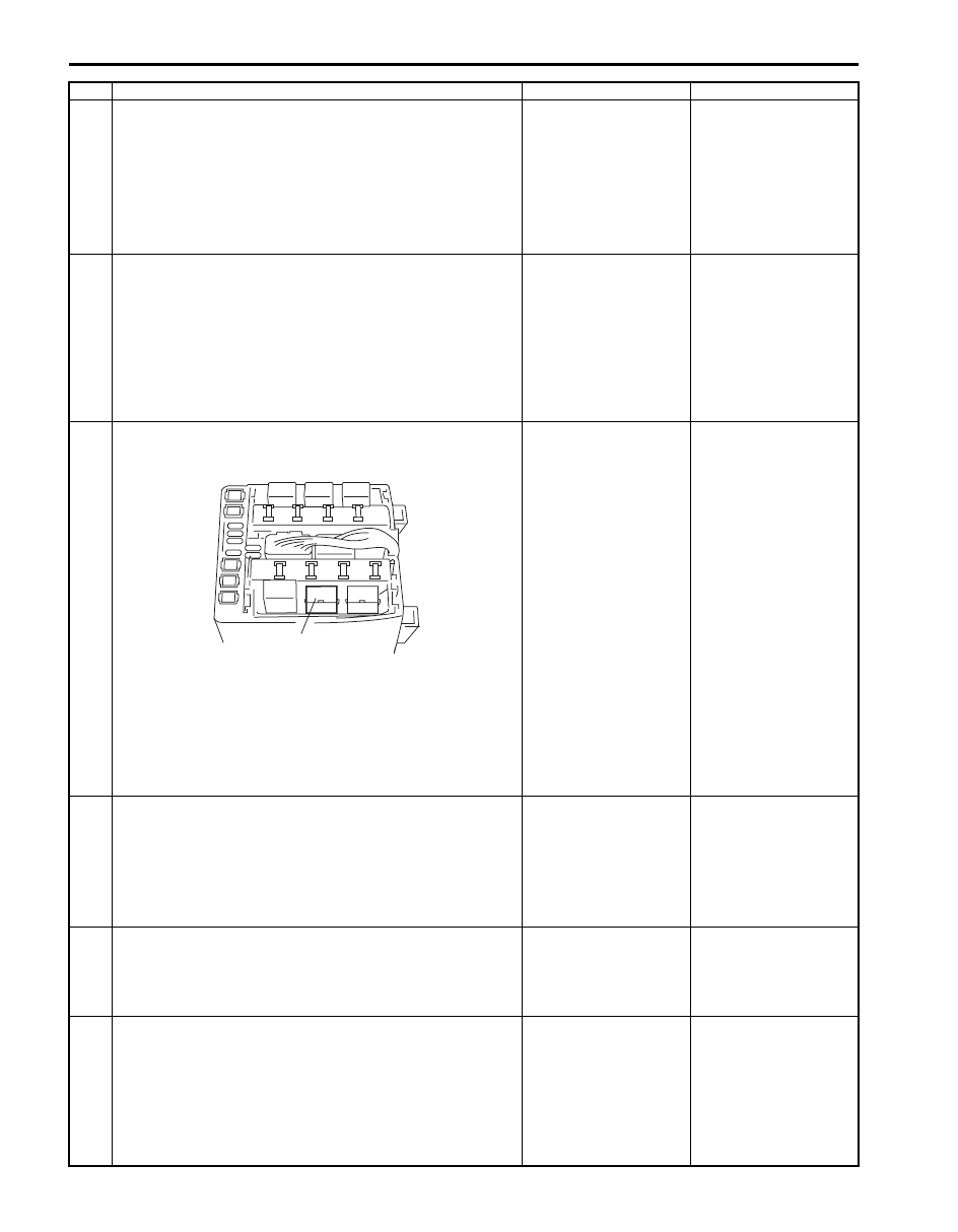
8
Main relay circuit check
1) Remove main relay (1) from fuse box No.2.
2) Check for proper connection to main relay connector at
“BLU/BLK” and “BLK/RED” wire terminals.
3) If OK, measure resistance between each “E23-2” and
“E23-3” wire terminals of ECM connector and “BLU/BLK”
wire terminal of main relay connector.
Is resistance 1
Ω
or less?
Go to Step 9.
“BLU/BLK” wire is open
circuit or high resistance
circuit.
9
Main relay circuit check
1) Remove main relay from fuse box No.2 with ignition
switch turned OFF.
2) Measure voltage between “BLK/RED” wire terminal of
main relay connector and body ground.
Is voltage 10 – 14 V?
Go to Step 10.
“BLK/RED” wire is open
circuit.
10 Main relay check
1) Check main relay referring to “Engine and Emission
Control System Relay Inspection in Section 1C”.
Is main relay in good condition?
“BLU” wire is open or
high resistance circuit.
Replace main relay.
11 Sensor 5 V power source circuit check
1) Connect connectors to ECM with ignition switch turned
OFF.
2) Turn ON ignition switch, measure each voltage between
“C37-45” and “C37-49” terminal of ECM connector and
vehicle body ground.
Is each voltage 4 – 6 V?
ECM power and ground
circuit is in good
condition.
Go to Step 12.
Step
Action
Yes
No
1
I5JB0C110017-01