Suzuki Grand Vitara JB627. Manual - part 4


  Index      Suzuki     Suzuki Grand Vitara JB627 - service repair manual


Search            


Content   ..  1  2  3  4  5  ..


Suzuki Grand Vitara JB627. Manual - part 4


00-13 Precautions: 

Brakes Caution and Note

S6JB0B0000014

CAUTION

!


All brake fasteners are important attaching 
parts in that they could affect the 
performance of vital parts and systems, and/
or could result in major repair expense. They 
must be replaced with one of same part 
number or with an equivalent part if 
replacement becomes necessary. Do not use 
a replacement part of lesser quality or 
substitute design. Torque values must be 
used as specified during reassembly to 
assure proper retention of all parts. There is 
to be no welding as it may result in extensive 
damage and weakening of the metal.


NOTE
Before inspecting and servicing brakes for 
vehicle equipped with ABS, make sure that 
ABS is in good condition.


Differential Gear Oil Note

S6JB0B0000015

NOTE

• When having driven through water, check 

immediately if water has entered (if so, oil 
is cloudy). Water mixed oil must be 
changed at once.

• Whenever vehicle is hoisted for any other 

service work than oil change, also be sure 
to check for oil leakage and status of 
breather hoses.


Repair Instructions

Electrical Circuit Inspection Procedure

S6JB0B0006001

While there are various electrical circuit inspection 
methods, described here is a general method to check 
its open and short circuit by using an ohmmeter and a 
voltmeter.

Open Circuit Check
Possible causes for the open circuit are as follows. As 
the cause is in the connector or terminal in many cases, 
they need to be checked particularly carefully.
• Loose connection of connector
• Poor contact of terminal (due to dirt, corrosion or rust 

on it, poor contact tension, entry of foreign object etc.)

• Wire harness being open
When checking system circuits including an electronic 
control unit such as ECM, TCM, ABS control module, 
etc., it is important to perform careful check, starting with 
items which are easier to check.

1) Disconnect negative cable from battery
2) Check each connector at both ends of the circuit 

being checked for loose connection. Also check lock 
condition of connector if equipped with connector 
lock.

3) Using a test male terminal, check both terminals of 

the circuit being checked for contact tension of its 
female terminal. Check each terminal visually for 
poor contact (possibly caused by dirt, corrosion, rust 
entry of foreign object, etc.). At the same time, check 
to make sure that each terminal is locked in the 
connector fully.

4) Using continuity check or voltage check the following 

procedure, check the wire harness for open circuit 
and poor connection with its terminals. Locate 
abnormality, if any.

I2RH01010049-01

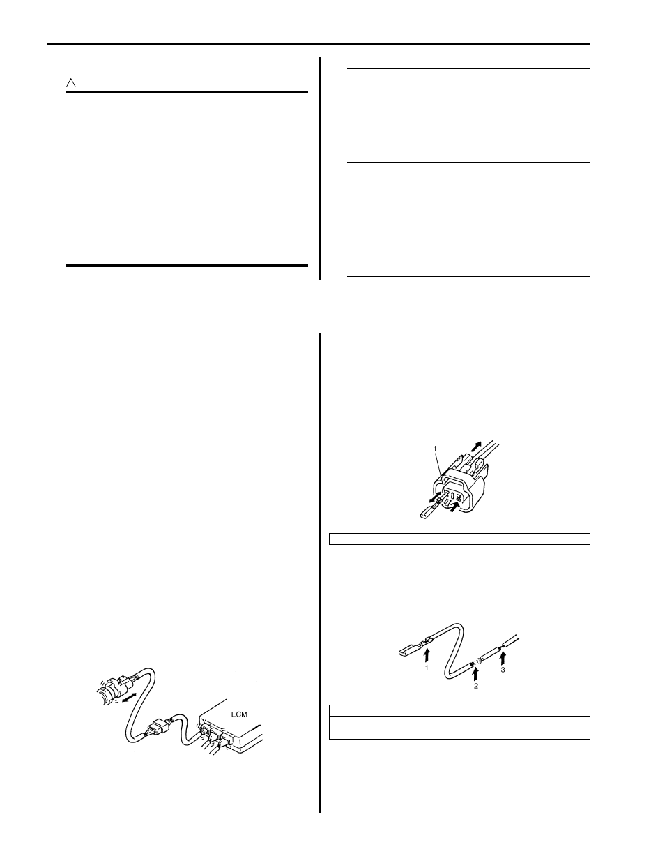
1. Check contact tension by inserting and removing just for once.

1. Looseness of crimping
2. Open
3. Thin wire (single strand of wire)

I2RH01010050-01

I2RH01010051-01

Precautions: 00-14

Continuity Check

1) Measure resistance between connector terminals at 

both ends of the circuit being checked (between “A-
1” and “C-1” in the figure). If no continuity is indicated 
(infinity or over limit), that means that the circuit is 
open between terminals “A-1” and “C-1”.

2) Disconnect the connector included in the circuit 

(connector-B in the figure) and measure resistance 
between terminals “A-1” and “B-1”.
If no continuity is indicated, that means that the 
circuit is open between terminals “A-1” and “B-1”. If 
continuity is indicated, there is an open circuit 
between terminals “B-1” and “C-1” or an abnormality 
in connector-B.

Voltage Check
If voltage is supplied to the circuit being checked, voltage 
check can be used as circuit check.

1) With all connectors connected and voltage applied to 

the circuit being checked, measure voltage between 
each terminal and body ground.
a) If measurements were taken as shown in the 

figure and results were as listed in the following, 
it means that the circuit is open between 
terminals “B-1” and “A-1”.

Voltage between each terminal and body 
ground
“C-1” and body ground: Approx. 5 V
“B-1” and body ground: Approx. 5 V
“A-1” and body ground: 0 V

b) Also, if measured values were as listed in the 

following, it means that there is a resistance 
(abnormality) of such level that corresponds to 
the voltage drop in the circuit between terminals 
“A-1” and “B-1”.

Voltage between
“C-1” and body ground: Approx. 5 V
“B-1” and body ground: Approx. 5 V
“A-1” and body ground: Approx. 3 V
“A-1” and “B-1”: 2V voltage drop

I2RH01010052-01

I2RH01010053-01

I5RH01000005-01

00-15 Precautions: 

Short Circuit Check (Wire Harness to Ground)

1) Disconnect negative cable at battery.
2) Disconnect connectors at both ends of the circuit to 

be checked.

NOTE
If the circuit to be checked is connected to 
other parts (1), disconnect all connectors of 
those parts.
Otherwise, diagnosis will be misled.


3) Measure resistance between terminal at one end of 

circuit (“A-1” terminal in the figure) and body ground. 
If continuity is indicated, it means that there is a short 
to ground between terminals “A-1” and “C-1” of the 
circuit.

4) Disconnect the connector included in circuit 

(connector B) and measure resistance between “A-
1” and body ground. 
If continuity is indicated, it means that the circuit is 
shorted to the ground between terminals “A-1” and 
“B-1”.

Intermittent and Poor Connection Inspection

S6JB0B0006002

Most intermittent are caused by faulty electrical 
connections or wiring, although a sticking relay or 
solenoid can occasionally be at fault. When checking it 
for proper connection, perform careful check of suspect 
circuits for:
• Poor mating of connector halves, or terminals not fully 

seated in the connector body (backed out).

• Dirt or corrosion on the terminals. The terminals must 

be clean and free of any foreign material which could 
impede proper terminal contact. However, cleaning 
the terminal with a sand paper or the like is prohibited. 

• Damaged connector body, exposing the terminals to 

moisture and dirt, as well as not maintaining proper 
terminal orientation with the component or mating 
connector.

1. To other parts

I5RH01000006-01

1. To other parts

I2RH01010056-01

I2RH01010057-01

Precautions: 00-16

• Improperly formed or damaged terminals.

Check each connector terminal in problem circuits 
carefully to ensure good contact tension by using the 
corresponding mating terminal.
If contact tension is not enough, reform it to increase 
contact tension or replace.

• Poor terminal-to-wire connection.

Check each wire harness in problem circuits for poor 
connection by shaking it by hand lightly. If any 
abnormal condition is found, repair or replace.

• Wire insulation which is rubbed through, causing an 

intermittent short as the bare area touches other 
wiring or parts of the vehicle.

• Wiring broken inside the insulation. This condition 

could cause continuity check to show a good circuit, 
but if only 1 or 2 strands of a multi-strand-type wire 
are intact, resistance could be far too high.
If any abnormality is found, repair or replace.

1. Check contact tension by inserting and removing just once.
2. Check each terminal for bend and proper alignment.

I5RH01000007-01

I2RH01010059-01

I2RH01010060-01


Content   ..  1  2  3  4  5  ..