Subaru Legacy IV (2008 year). Manual - part 993


  Index      Subaru     Subaru Legacy IV - service repair manual 2008 year


Search            


Content   ..  991  992  993  994   ..


Subaru Legacy IV (2008 year). Manual - part 993


AC(diag)-24

Diagnostic Procedure for Actuators

HVAC SYSTEM (AUTO A/C) (DIAGNOSTICS)

B: MODE DOOR ACTUATOR

TROUBLE SYMPTOM:
Air flow outlet is not changed.
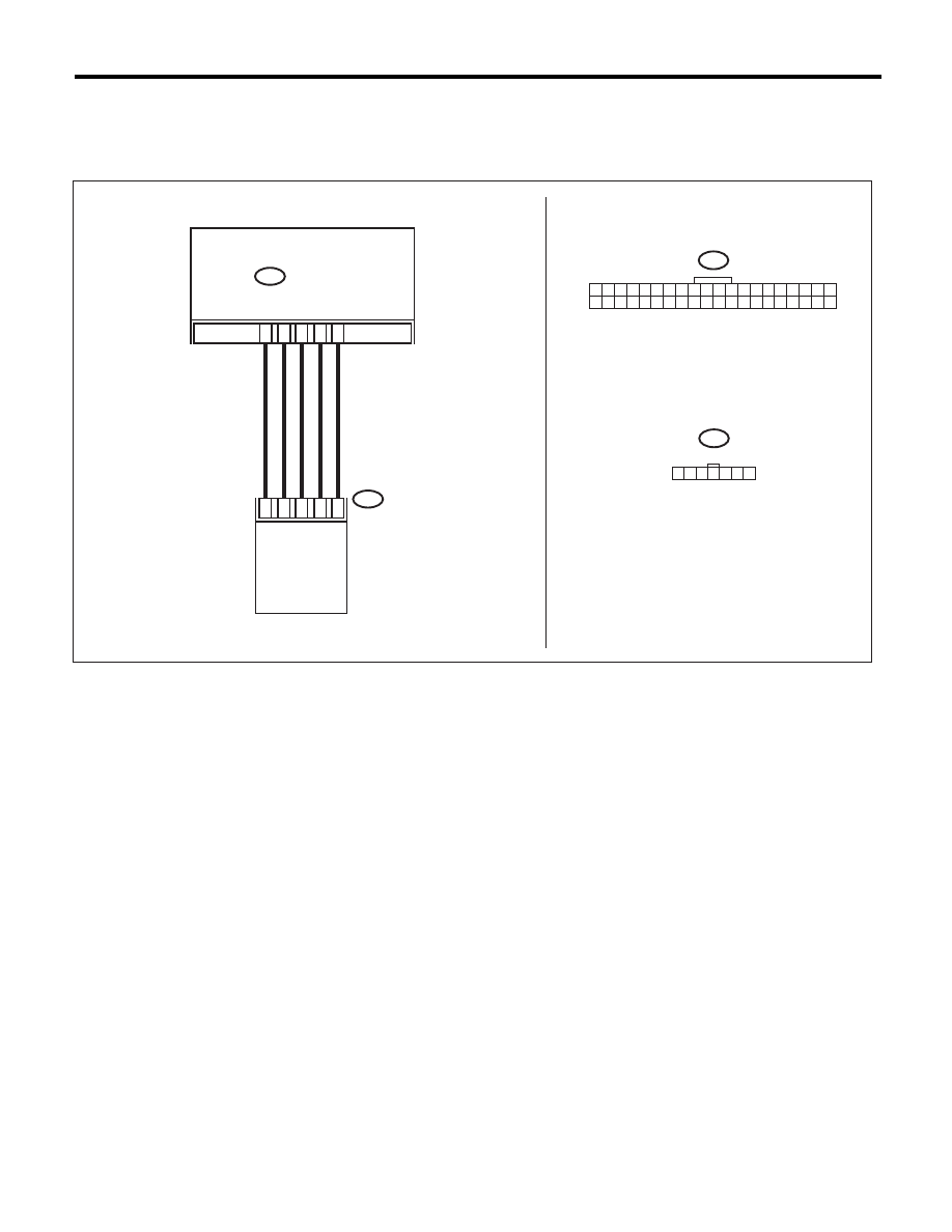
WIRING DIAGRAM:

AC-01647

B77

B282

B282

B77

36

1

7

6

27

16

5

3

8

3

1 2 3 4 5 6 7

1 2 3 4 5 6 7 8 9 10

21 22 23 24 25 26 27 28 29 30

11 12 13 14 15 16 17 18 19 20
31 32 33 34 35 36 37 38 39 40

AUTO A/C 
CONTROL MODULE

MODE DOOR 
ACTUATOR

AC(diag)-25

Diagnostic Procedure for Actuators

HVAC SYSTEM (AUTO A/C) (DIAGNOSTICS)

Step

Check

Yes

No

1

CHECK POWER SUPPLY FOR MODE DOOR 
ACTUATOR POSITION SENSOR.
1) Turn the ignition switch to OFF.
2) Disconnect the mode door actuator connec-
tor.
3) Turn the ignition switch and AUTO switch to 
ON.
4) Measure the voltage between auto A/C con-
trol module connector terminals.

Connector & terminal

(B282) No. 8 (+) — (B282) No. 27 (–):

Is the voltage approx. 5 V?

Go to step 2.

Replace the auto 
A/C control mod-
ule.

2

CHECK POWER SUPPLY FOR MODE DOOR 
ACTUATOR.
Measure the voltage between auto A/C control 
module connector and chassis ground after 
turning the air flow control switch to FACE posi-
tion.

Connector & terminal

(B282) No. 16 (+) — Chassis ground (–):

Is the voltage 7 V (at normal 
temperature)?

Go to step 3.

Replace the auto 
A/C control mod-
ule.

3

CHECK POWER SUPPLY FOR MODE DOOR 
ACTUATOR.
Measure the voltage between auto A/C control 
module connector and chassis ground after 
turning the air flow control switch to DEF posi-
tion.

Connector & terminal

(B282) No. 36 (+) — Chassis ground (–):

Is the voltage 7 V (at normal 
temperature)?

Go to step 4.

Replace the auto 
A/C control mod-
ule.

4

CHECK HARNESS BETWEEN AUTO A/C 
CONTROL MODULE AND MODE DOOR AC-
TUATOR.
1) Turn the A/C and ignition switch to OFF.
2) Disconnect the auto A/C control module 
connector.
3) Measure the resistance between auto A/C 
control module and mode door actuator con-
nector.

Connector & terminal

(B77) No. 1 — (B282) No. 27:
(B77) No. 3 — (B282) No. 8:
(B77) No. 5 — (B282) No. 3:
(B77) No. 6 — (B282) No. 36:
(B77) No. 7 — (B282) No. 16:

Is the resistance less than 1 

:? Go to step 5.

Repair the harness 
between auto A/C 
control module and 
mode door actua-
tor.

5

CHECK MODE DOOR ACTUATOR POSI-
TION SWITCH SIGNAL.
1) Connect the connector of auto A/C control 
module and mode door actuator.
2) Turn the ignition switch and AUTO switch to 
ON.
3) Check the voltage between auto A/C control 
module connector terminals while changing the 
mode between DEF and FACE.

Connector & terminal

(B282) No. 3 (+) — (B282) No. 27 (–):

Does the voltage change 
between 1 V (DEF) and 4 V 
(FACE)?

Go to step 6.

Replace the mode 
door actuator.

6

CHECK POOR CONTACT.
Check poor contact of auto A/C control module 
and connector.

Is there poor contact in connec-
tor?

Repair the connec-
tor.

Replace the auto 
A/C control mod-
ule.

AC(diag)-26

Diagnostic Procedure for Actuators

HVAC SYSTEM (AUTO A/C) (DIAGNOSTICS)

C: AIR MIX DOOR ACTUATOR

TROUBLE SYMPTOM:
Outlet air temperature does not change.
WIRING DIAGRAM:

B235

B282

B282

B235

3

7

6

5

1

1

3 4 5

7

2

6

B390

1

7

6

5

3

B390

27

17

4

18

8

38

24

37

AC-01648

1 2 3 4 5 6 7 8 9 10

21 22 23 24 25 26 27 28 29 30

11 12 13 14 15 16 17 18 19 20
31 32 33 34 35 36 37 38 39 40

AUTO A/C 
CONTROL MODULE

DRIVER'S
AIR MIX DOOR 
ACTUATOR

PASSENGER'S 
AIR MIX DOOR 
ACTUATOR

AC(diag)-27

Diagnostic Procedure for Actuators

HVAC SYSTEM (AUTO A/C) (DIAGNOSTICS)

Step

Check

Yes

No

1

CHECK POWER SUPPLY FOR AIR MIX 
DOOR ACTUATOR POSITION SWITCH.
1) Turn the ignition switch to OFF.
2) Disconnect the air mix door actuator con-
nector.
3) Turn the ignition switch and AUTO switch to 
ON.
4) Measure the voltage between auto A/C con-
trol module connector terminals.

Connector & terminal

(B282) No. 8 (+) — (B282) No. 27 (–):

Is the voltage approx. 5 V?

Go to step 2.

Replace the auto 
A/C control mod-
ule.

2

CHECK POWER SUPPLY FOR AIR MIX 
DOOR ACTUATOR.
Measure the voltage between auto A/C control 
module connector and chassis ground after 
turning the temperature control dial to maxi-
mum COOL position.

Connector & terminal

Driver’s side

(B282) No. 18 (+) — Chassis ground (–):

Passenger’s side

(B282) No. 17 (+) — Chassis ground (–):

Is the voltage 7 V (at normal 
temperature)?

Go to step 3.

Replace the auto 
A/C control mod-
ule.

3

CHECK POWER SUPPLY FOR AIR MIX 
DOOR ACTUATOR.
Measure the voltage between auto A/C control 
module connector and chassis ground after 
turning the temperature control dial to maxi-
mum HOT position.

Connector & terminal

Driver’s side

(B282) No. 38 (+) — Chassis ground (–):

Passenger’s side

(B282) No. 37 (+) — Chassis ground (–):

Is the voltage 7 V (at normal 
temperature)?

Go to step 4.

Replace the auto 
A/C control mod-
ule.

4

CHECK HARNESS BETWEEN AUTO A/C 
CONTROL MODULE AND AIR MIX DOOR 
ACTUATOR.
1) Turn the A/C and ignition switch to OFF.
2) Disconnect the auto A/C control module 
connector.
3) Measure the resistance between auto A/C 
control module and air mix door actuator con-
nector.

Connector & terminal

Driver’s side

(B390) No. 1 — (B282) No. 27:
(B390) No. 3 — (B282) No. 8:
(B390) No. 5 — (B282) No. 24:
(B390) No. 6 — (B282) No. 38:
(B390) No. 7 — (B282) No. 18:

Passenger’s side

(B235) No. 1 — (B282) No. 8:
(B235) No. 3 — (B282) No. 27:
(B235) No. 5 — (B282) No. 4:
(B235) No. 6 — (B282) No. 17:
(B235) No. 7 — (B282) No. 37:

Is the resistance less than 1 

:? Go to step 5.

Repair the harness 
between auto A/C 
control module and 
air mix door actua-
tor.


Content   ..  991  992  993  994   ..