Subaru Legacy IV (2008 year). Manual - part 991


  Index      Subaru     Subaru Legacy IV - service repair manual 2008 year


Search            


Content   ..  989  990  991  992   ..


Subaru Legacy IV (2008 year). Manual - part 991


AC(diag)-16

Diagnostics for A/C System Malfunction

HVAC SYSTEM (AUTO A/C) (DIAGNOSTICS)

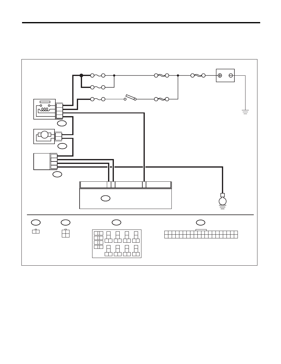
B: BLOWER MOTOR DOES NOT ROTATE

TROUBLE SYMPTOM:
• Blower motor does not rotate.
• Blower motor does not rotate in “HI”.
WIRING DIAGRAM:

11

12

32

B225

B87

B86

F/B No. 27

F/B No. 28

F/B No. 22

SBF-3

MAIN SBF

SBF-6

2
4
1

21
23
24
22

2
1

B87

B86

3 4

1 2

B282

E

M

3

1 2

B225

AC-01644

B282

13
14

15 16

17

27

24

25
26

20

21
22

23

29
30

31

28

32

35

33
34

37
38

39

36

40

8

9

10

11 12

1

2

5

3

4

7

6

19

18

1 2 3 4 5 6 7 8 9 10 11 12 13 14 15 16 17 18 19 20

21 22 23 24 25 26 27 28 29 30 31 32 33 34 35 36 37 38 39 40

BATTERY

IGNITION
SWITCH

BLOWER MOTOR 
RELAY

BLOWER MOTOR

POWER
TRANSISTOR

AUTO A/C CONTROL MODULE

AC(diag)-17

Diagnostics for A/C System Malfunction

HVAC SYSTEM (AUTO A/C) (DIAGNOSTICS)

Step

Check

Yes

No

1

CHECK FUSE.
1) Remove fuse No. 22, 27 and 28 from fuse & 
relay box.
2) Check the condition of fuse.

Is any fuse blown out?

Replace the fuse.

Go to step 2.

2

CHECK POWER SUPPLY FOR BLOWER 
MOTOR.
1) Turn the ignition switch to ON.
2) Turn the blower switch to ON.
3) Measure the voltage between blower motor 
and chassis ground.

Connector & terminal

(B87) No. 2 (+) — Chassis ground (–):

Is the voltage 10 V or more?

Go to step 3.

Repair the open 
circuit of blower 
motor power sup-
ply line harness.

3

CHECK BLOWER MOTOR RELAY.
1) Turn the ignition switch to OFF.
2) Remove the blower motor relay.
3) Connect the battery positive (+) terminal to 
terminal No. 23 of blower motor relay, and neg-
ative (–) terminal to terminal No. 24.
4) Measure the resistance between terminals 
No. 21 and No. 22.

Terminals

(B225) No. 21 — (B225) No. 22:

Is the resistance less than 1 

:? Go to step 4.

Replace the blower 
motor relay.

4

CHECK BLOWER MOTOR.
1) Disconnect the connector from blower 
motor.
2) Connect the battery positive (+) terminal to 
terminal No. 2 of blower motor connector, and 
negative (–) terminal to terminal No. 1.
3) Make sure the blower motor runs.

Does the blower motor run?

Go to step 5.

Replace the blower 
motor.

5

CHECK POOR CONTACT.
Check poor contact of auto A/C control module 
connector.

Is there poor contact in connec-
tor?

Repair the connec-
tor.

Replace the auto 
A/C control mod-
ule.

AC(diag)-18

Diagnostics for A/C System Malfunction

HVAC SYSTEM (AUTO A/C) (DIAGNOSTICS)

C: COMPARTMENT TEMPERATURE DOES NOT CHANGE, OR A/C SYSTEM 

DOES NOT RESPOND PROMPTLY

WIRING DIAGRAM:

E

E

E

MAIN SBF

SBF-6

F/B No.22

B360

F109

B143

B:

F37

A:

F35

C:

B143

B:

F37

A:

F35

C:

1

9

F24

1

2

B361

F108

B136

C:

B282

F27

B10

14

9

14

16

15

17

C3

C7

A4

B13

2

4

1

3

C9

C24

C33

22

15

A13

B20

C12

A/C RELAY

B282

B143

F109

B:

F37

A:

F35

C:

1 2 3 4

5 6 7 8 9

10 11 12 13 14

15 16 17 18 19 20

1 2

3 4 5

6 7 8 9 10 11 12

2 3 4

5 6 7 8 9

11 12 13 14

17 18 19 20

1

10

15 16

B361

1 2 3

4 5 6

7 8 9 10 11 12 13 14

B136

C:

1

2

8 9

5

6

3

4

10 11 12

19 20 21

29 30

31

13 14 15 16

17

27

28

18

22 23 24 25 26

7

32 33 34 35

F24

1 2

B10

2

3

1

4

B360

1 2 3

4 5 6 7

8 9 10 11 12 13 14 15 16

F108

1
9

2 3

8

10

4

11 12 13 14 15 16

5 6 7

17 18

1 2 3 4 5 6 7 8 9 10

21 22 23 24 25 26 27 28 29 30

11 12 13 14 15 16 17 18 19 20
31 32 33 34 35 36 37 38 39 40

F27

12

11

10

18
19

16

15

17

9

20 21 22

8

4 5

3

2

1

7

6

14

13

3 4

1 2

8 9 10 11

12 13 14 15 16 17 18 19 20 21 22 23 24

5

6 7

AC-01683

IGNITION SWITCH

THROUGH JOINT 
CONNECTOR

THROUGH JOINT 
CONNECTOR

MAIN FUSE 
BOX

PRESSURE
SWITCH

MAGNET 
CLUTCH

MAIN FUSE 
BOX

AUTO A/C 
CONTROL 
MODULE

ECM

BATTERY

AC(diag)-19

Diagnostics for A/C System Malfunction

HVAC SYSTEM (AUTO A/C) (DIAGNOSTICS)

Step

Check

Yes

No

1

CHECK FUSE.
1) Turn the ignition switch to OFF.
2) Remove the fuse No. 22 from fuse & relay 
box.
3) Check the condition of fuse.

Is the fuse blown out?

Replace the fuse.

Go to step 2.

2

CHECK POWER SUPPLY TO A/C RELAY 
AND AUTO A/C CONTROL MODULE.
1) Disconnect the A/C relay and auto A/C con-
trol module harness connector.
2) Turn the ignition switch to ON.
3) Measure the voltage between A/C relay 
connector terminal and chassis ground.
4) Measure the voltage between auto A/C con-
trol module harness connector terminal and 
chassis ground.

Connector & terminal

(F27) No. 17 (+) — Chassis ground (–):
(B282) No. 22 (+) — Chassis ground (–):

Is the voltage 10 V or more?

Go to step 5.

Go to step 3.

3

CHECK POWER SUPPLY FOR PRESSURE 
SWITCH.
1) Turn the ignition switch to OFF.
2) Disconnect the pressure switch harness 
connector.
3) Turn the ignition switch to ON.
4) Measure the voltage between pressure 
switch harness connector terminal and chassis 
ground.

Connector & terminal

(B10) No. 2 (+) — Chassis ground (–):

Is the voltage 10 V or more?

Go to step 4.

Check for open or 
short circuit in the 
harness between 
fuse and pressure 
switch.

4

CHECK HARNESS BETWEEN PRESSURE 
SWITCH AND A/C RELAY, AUTO A/C CON-
TROL MODULE.
1) Turn the ignition switch to OFF.
2) Measure the resistance of harness between 
pressure switch connector and A/C relay con-
nector.
3) Measure the resistance of harness between 
pressure switch connector and auto A/C control 
module connector.

Connector & terminal

(B10) No. 1 — (F27) No. 17:
(B10) No. 1 — (B282) No. 22:

Is the resistance less than 1 

:? Check the pres-

sure switch. <Ref. 
to AC-42, INSPEC-
TION, Pressure 
Switch (Triple 
Pressure Switch).>

Repair the har-
ness.

5

CHECK POWER SUPPLY FOR A/C RELAY.
Measure the voltage between A/C relay con-
nector terminal and chassis ground.

Connector & terminal

(F27) No. 14 (+) — Chassis ground (–):

Is the voltage 10 V or more?

Go to step 6.

Check open or 
short circuit of har-
ness between fuse 
and A/C relay.

6

CHECK A/C RELAY.
Check the A/C relay. <Ref. to AC-41, INSPEC-
TION, Relay and Fuse.>

Is there a malfunction in the A/C 
relay?

Replace the A/C 
relay.

Go to step 7.


Content   ..  989  990  991  992   ..