Subaru Legacy IV (2008 year). Manual - part 984
AC-39
Evaporator
HVAC SYSTEM (HEATER, VENTILATOR AND A/C)
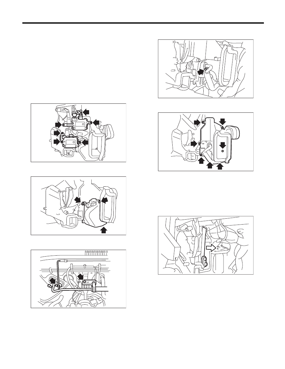
18.Evaporator
A: REMOVAL
1) Using the refrigerant recovery system, drain the
refrigerant. <Ref. to AC-22, PROCEDURE, Refrig-
erant Recovery Procedure.>
2) Disconnect the ground cable from the battery.
3) Remove the blower motor unit assembly. <Ref.
to AC-28, REMOVAL, Blower Motor Unit Assem-
bly.>
4) Disconnect the connector, remove the screw
and then remove the air-mix door actuator and
mode door actuator.
5) Disconnect the connector, remove the pipe cov-
er and evaporator sensor.
6) Remove the bolts securing expansion valve and
pipe in engine compartment.
7) Remove the bolt which holds the pipe to the
evaporator.
8) Remove the screws and clip to remove the evap-
orator cover.
9) Pull out the evaporator (A) in the direction of the
arrow.
CAUTION:
If the evaporator is replaced, add an appropri-
ate amount of compressor oil to evaporator.
<Ref. to AC-27, REPLACEMENT, Compressor
Oil.>
B: INSTALLATION
Install in the reverse order of removal.
AC-00923
AC-00924
AC-00925
AC-00926
AC-01187
AC-00928
(A)