Subaru Legacy IV (2008 year). Manual - part 983


  Index      Subaru     Subaru Legacy IV - service repair manual 2008 year


Search            


Content   ..  981  982  983  984   ..


Subaru Legacy IV (2008 year). Manual - part 983


AC-35

Control Unit (Auto A/C Model)

HVAC SYSTEM (HEATER, VENTILATOR AND A/C)

14.Control Unit (Auto A/C Model)
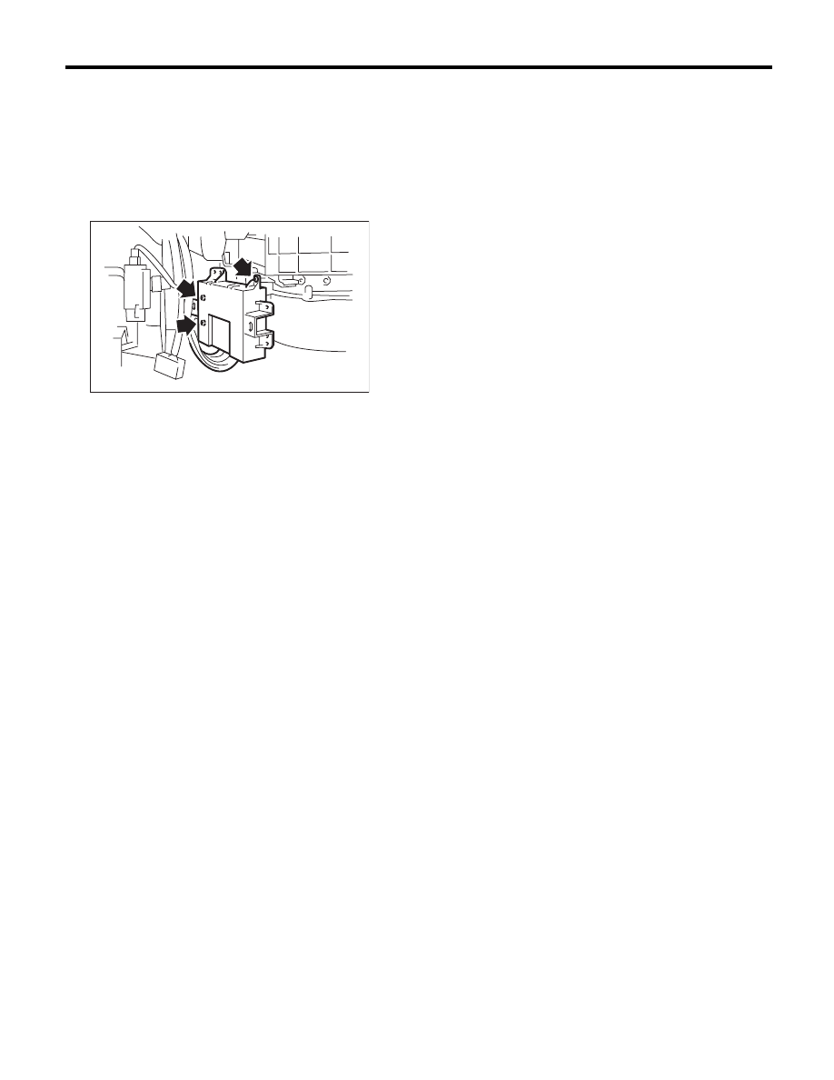
A: REMOVAL

1) Disconnect the ground cable from the battery.
2) Remove the glove box. <Ref. to EI-52, REMOV-
AL, Glove Box.>
3) Remove the screw, disconnect the connector
and remove the control unit.

B: INSTALLATION

Install in the reverse order of removal.

AC-00919

AC-36

Compressor

HVAC SYSTEM (HEATER, VENTILATOR AND A/C)

15.Compressor

A: INSPECTION

1. MAGNETIC CLUTCH CLEARANCE

Check the clearance of the entire circumference
around the drive plate and pulley.

Standard:

0.45

r

0.15 mm (0.0177

r

0.0059 in)

2. MAGNETIC CLUTCH OPERATION

1) Disconnect the compressor connector.
2) Connect the battery positive (+) terminal to ter-
minal No. 1 of the compressor connector, and the
negative (–) terminal to terminal No. 2.

3) Check the magnet clutch engagement.
If there is a problem, replace the compressor.

B: REMOVAL

1) Perform compressor oil return operation. <Ref.
to AC-27, PROCEDURE, Compressor Oil.>
2) Turn the A/C switch to OFF and stop the engine.
3) Using the refrigerant recovery system, drain the
refrigerant. <Ref. to AC-22, PROCEDURE, Refrig-
erant Recovery Procedure.>
4) Disconnect the ground cable from the battery.
5) Remove the V-belts. <Ref. to ME(H4SO)-38,
REMOVAL, V-belt.> <Ref. to ME(H4DOTC)-41,
REMOVAL, V-belt.> <Ref. to ME(H6DO)-42, RE-
MOVAL, V-belt.>
6) Remove the generator. <Ref. to SC(H4SO)-14,
REMOVAL, Generator.>
7) Remove the bolt and remove the low-pressure
hose and high-pressure hose.

8) Disconnect the compressor harness from the
body harness.
9) Remove the bolts and remove the compressor
bracket.
• H4 model

• H6 model

10) Remove the bolts, then remove the bracket
from the compressor.

C: INSTALLATION

1) Install in the reverse order of removal.
2) Replace the O-rings on low-/high-pressure hos-
es with new parts, then apply compressor oil.
3) After replacing the compressor, adjust the
amount of compressor oil. <Ref. to AC-27, PRO-
CEDURE, Compressor Oil.>
4) Charge with refrigerant. <Ref. to AC-23, PRO-
CEDURE, Refrigerant Charging Procedure.>

Tightening torque:

Refer to “COMPONENT” of “General Descrip-
tion”. <Ref. to AC-11, AIR CONDITIONING 
UNIT, COMPONENT, General Description.> 
<Ref. to AC-12, COMPRESSOR, COMPO-
NENT, General Description.>

AC-00771

AC-00772

AC-00773

AC-00920

AC-00774

AC-37

Condenser

HVAC SYSTEM (HEATER, VENTILATOR AND A/C)

16.Condenser

A: REMOVAL

1) Using the refrigerant recovery system, drain the
refrigerant. <Ref. to AC-22, PROCEDURE, Refrig-
erant Recovery Procedure.>
2) Disconnect the ground cable from the battery.
3) Disconnect the pressure hose and pipe from the
condenser.

4) Remove the radiator bracket (A) and hood stay (B).

5) Remove the front grille. <Ref. to EI-24, REMOV-
AL, Front Grille.>
6) Remove two bolts. While lifting the condenser,
pull out through space between the radiator and the
radiator panel.

CAUTION:
• Be careful not to damage the condenser fins.
If a damaged fin is found, repair it using a thin
screwdriver.
• When replacing the condenser, add an ap-
propriate amount of compressor oil to the com-
pressor. <Ref. to AC-27, REPLACEMENT,
Compressor Oil.>

B: INSTALLATION

1) Install in the reverse order of removal.

CAUTION:
Replace the O-rings on hoses or pipes with new
parts, and then apply compressor oil. Confirm
that lower guide (A) of condenser fits into holes
on radiator panel.

2) Charge with refrigerant. <Ref. to AC-23, PRO-
CEDURE, Refrigerant Charging Procedure.>

Tightening torque:

Refer to “COMPONENT” of “General Descrip-
tion”. <Ref. to AC-11, AIR CONDITIONING 
UNIT, COMPONENT, General Description.> 
<Ref. to CO(H4SO)-4, RADIATOR & RADIA-
TOR FAN, COMPONENT, General Descrip-
tion.>

C: INSPECTION

1) Check to see that the condenser fins are not
clogged with debris or insects. Blow with com-
pressed air or flush fins with water as needed.
2) Inspect for oil leakage from the condenser. If a
failure is found, replace the condenser with a new
part.

AC-00775

AC-00776

(A)

(A)

(B)

AC-00777

AC-00631

(A)

AC-38

Heater and Cooling Unit

HVAC SYSTEM (HEATER, VENTILATOR AND A/C)

17.Heater and Cooling Unit

A: REMOVAL

1) Disconnect the ground cable from the battery.
2) Using the refrigerant recovery system, drain the
refrigerant. <Ref. to AC-22, PROCEDURE, Refrig-
erant Recovery Procedure.>
3) Drain engine coolant from the radiator.
4) Remove the bolts securing expansion valve and
pipe in engine compartment. Release the heater
hose clamps in engine compartment to remove the
hoses.

5) Remove the instrument panel. <Ref. to EI-57,
REMOVAL, Instrument Panel Assembly.>
6) Remove the support beam.
7) Remove the blower motor unit assembly. <Ref.
to AC-28, REMOVAL, Blower Motor Unit Assem-
bly.>
8) Disconnect the actuator connector.
9) Remove the bolt and nuts and remove the heat-
er and cooling unit.

B: INSTALLATION

1) Install in the reverse order of removal.
2) Charge with refrigerant. <Ref. to AC-23, PRO-
CEDURE, Refrigerant Charging Procedure.>

Tightening torque:

Refer to “COMPONENT” of “General Descrip-
tion”. <Ref. to AC-6, HEATER COOLING 
UNIT, COMPONENT, General Description.>

AC-00921

AC-01599


Content   ..  981  982  983  984   ..