Subaru Legacy IV (2008 year). Manual - part 971
PS-46
Oil Pump
POWER ASSISTED SYSTEM (POWER STEERING)
B: INSTALLATION
1. H4 MODEL
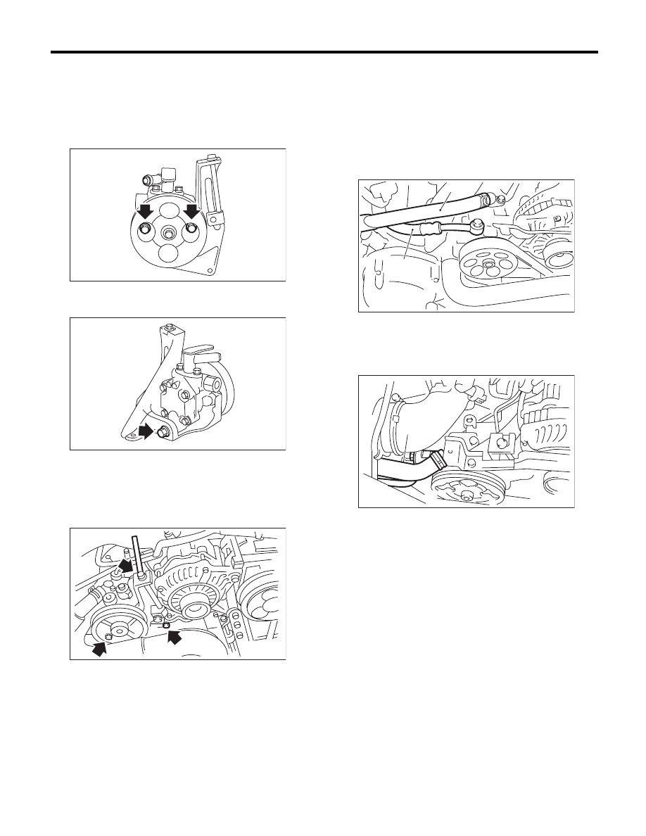
1) Install the oil pump to the bracket.
Tightening torque:
15.7 N·m (1.6 kgf-m, 11.6 ft-lb)
Tightening torque:
48.4 N·m (4.9 kgf-m, 35.7 ft-lb)
2) Attach the installation bolts of the power steering
pump bracket.
Tightening torque:
<Ref. to PS-6, OIL PUMP, COMPONENT, Gen-
eral Description.>
3) After installing the oil pump, fill the fluid while ro-
tating the pulley by hand to bleed air from the oil
pump.
CAUTION:
Always fill the oil pump with the fluid to prevent
abnormal noise and seizure of the oil pump.
4) Connect the pressure hose and suction hose.
Tightening torque:
Eye bolt
40 N·m (4.1 kgf-m, 29.5 ft-lb)
CAUTION:
Be careful not to twist hoses. Twisted hoses
may contact other parts.
• Non-turbo model
• Turbo model
5) Connect the power steering pressure switch
connector.
6) Install the V-belts to the oil pump.
7) Check the tension of the V-belt.
<Ref. to ME(H4SO)-40, INSPECTION, V-belt.>
8) Tighten the lock bolt of the belt tension nut.
Tightening torque:
25 N·m (2.5 kgf-m, 18.4 ft-lb)
9) Install the pulley belt cover.
10) Install the air intake duct.
<Ref. to IN(H4DOTC)-9, INSTALLATION, Air In-
take Duct.> <Ref. to IN(H4SO)-8, INSTALLATION,
Air Intake Duct.>
11) Connect the ground cable to battery.
PS-00128
PS-00137
PS-00188
(1) Suction hose
(2) Pressure hose
(1) Suction hose
(2) Pressure hose
PS-00688
(1)
(2)
(2)
PS-00459
(1)