Subaru Legacy IV (2008 year). Manual - part 969


  Index      Subaru     Subaru Legacy IV - service repair manual 2008 year


Search            


Content   ..  967  968  969  970   ..


Subaru Legacy IV (2008 year). Manual - part 969


PS-38

Pipe Assembly

POWER ASSISTED SYSTEM (POWER STEERING)

6. Pipe Assembly

A: REMOVAL

1) Disconnect the ground cable from the battery.
2) Lift up the vehicle, and then remove the front
crossmember support plate and jack-up plate.
• Large type

• Small type

3) Remove the one pipe joint at the center of the
gearbox, and connect the vinyl hose to the pipe and
the joint. Discharge the fluid by turning the steering
wheel fully clockwise and counterclockwise. Dis-
charge the fluid similarly from other pipes.

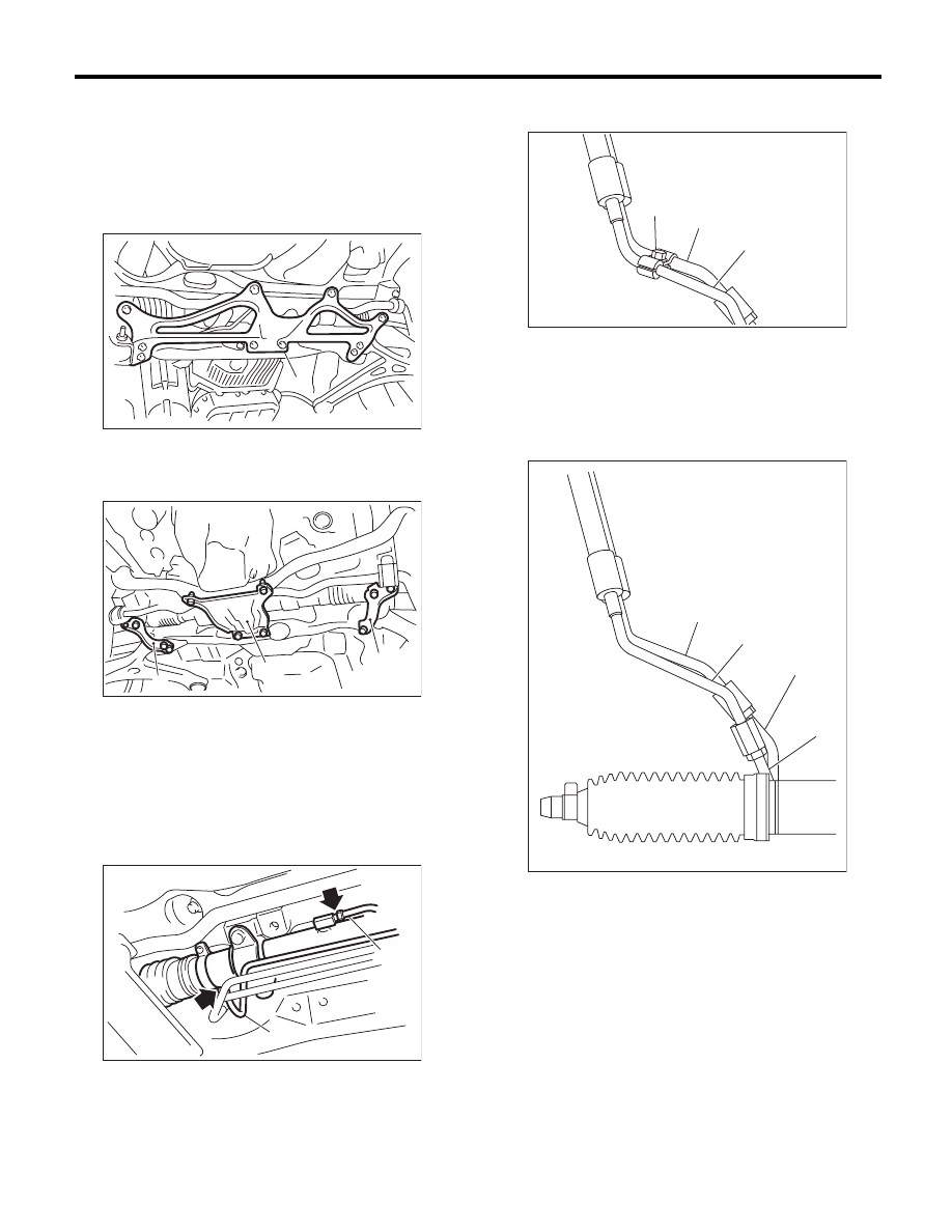
4) Remove the clamp E from return hose and pres-
sure hose.

5) Disconnect the pipe D from return hose and pipe
C from pressure hose.

6) Remove the air intake duct. <Ref. to
IN(H4DOTC)-9, REMOVAL, Air Intake Duct.>
<Ref. to IN(H4SO)-8, REMOVAL, Air Intake Duct.>

(1) Front crossmember support plate

(1) Crossmember support plate

(2) Jack-up plate

(1) Pipe A

(2) Pipe B

PS-00445

(1)

FS-00105

(2)

(1)

(1)

(2)

PS-00553

(1)

(1) Return hose

(2) Pressure hose

(3) Clamp E

(1) Pipe C

(2) Pipe D

(3) Pressure hose

(4) Return hose

PS-00537

(3)

(1)

(2)

PS-00538

(4)

(3)

(2)

(1)

PS-39

Pipe Assembly

POWER ASSISTED SYSTEM (POWER STEERING)

7) Disconnect the suction hose and pressure hose
from oil pump.

8) Disconnect the suction hose and return hose
from the reservoir tank.

9) Remove the hose bracket and take out the hose
assembly from vehicle.

B: INSTALLATION

1) Temporarily tighten the hose bracket bolt.

2) Install the plastic clip to the pressure hose and
suction hose.

CAUTION:
Align the installation position of the plastic clip
with the protector edge of the suction hose.

(1) Suction hose

(2) Pressure hose

(1) Reservoir tank

(2) Suction hose

(3) Return hose

(1) Hose ASSY

(2) Hose bracket

(1)

PS-00460

(2)

PS-00799

(3)

(1)

(2)

PS-00624

(2)

(1)

(1) Hose ASSY

(2) Hose bracket

(1) Plastic clip

(2) Protector

(3) Suction hose

(4) Pressure hose

PS-00624

(2)

(1)

PS-00455

(1)

(2)

(3)

(4)

PS-40

Pipe Assembly

POWER ASSISTED SYSTEM (POWER STEERING)

3) Connect the suction hose and return hose to the
reservoir tank.

CAUTION:
Firmly insert the plastic clip of return hose to
the bracket.

4) Connect the suction hose and pressure hose to
the oil pump. Tighten the eye bolt of pressure hose.

Tightening torque:

40 N·m (4.1 kgf-m, 29.5 ft-lb)

5) Temporarily connect pressure hose and pipe C,
and the return hose and pipe D. Place clamp E at
the position shown in the figure, and tighten the bolt
temporarily.

6) Tighten clamp E.

Tightening torque:

7.4 N·m (0.75 kgf-m, 5.4 ft-lb)

7) Tighten the pressure hose and pipe C, and the
return hose and pipe D.

Tightening torque:

15 N·m (1.5 kgf-m, 10.8 ft-lb)

(1) Reservoir tank

(2) Suction hose

(3) Return hose

(1) Suction hose

(2) Pressure hose

PS-00799

(3)

(1)

(2)

(1)

PS-00460

(2)

(1) Return hose

(2) Pressure hose

(3) Approx. 18 mm (0.71 in)

(4) Clamp E

(5) Pipe C

(6) Pipe D

PS-00539

(4)

(3)

(2)

(6)

(5)

(1)

PS-41

Pipe Assembly

POWER ASSISTED SYSTEM (POWER STEERING)

8) Connect pipes A and B to the four pipe joints of
the gearbox.

Tightening torque:

Refer to “COMPONENT” of “General Descrip-
tion”. <Ref. to PS-4, POWER ASSISTED SYS-
TEM, COMPONENT, General Description.>

9) Install the front crossmember support plate and
jack-up plate.
10) Lower the vehicle.
11) Tighten the bolts which hold the hose bracket.

Tightening torque:

10 N·m (1.02 kgf-m, 7.4 ft-lb)

12) Install the air intake duct. <Ref. to
IN(H4DOTC)-9, INSTALLATION, Air Intake Duct.>
<Ref. to IN(H4SO)-8, INSTALLATION, Air Intake
Duct.>
13) Connect the ground cable to battery.
14) Fill with the specified fluid.

CAUTION:
Never start the engine before filling with fluid;
otherwise the vane pump may become seized.
15) Finally, check the clearance between pipes or
hoses as shown in the figure indicated in “General
Diagnostic Table”. <Ref. to PS-58, INSPECTION
OF CLEARANCE, INSPECTION, General Diag-
nostic Table.>

(1) Pipe A

(2) Pipe B

(1) Hose ASSY

(2) Hose bracket

(2)

PS-00553

(1)

PS-00624

(2)

(1)


Content   ..  967  968  969  970   ..