Subaru Legacy IV (2008 year). Manual - part 966


  Index      Subaru     Subaru Legacy IV - service repair manual 2008 year


Search            


Content   ..  964  965  966  967   ..


Subaru Legacy IV (2008 year). Manual - part 966


PS-26

Steering Gearbox

POWER ASSISTED SYSTEM (POWER STEERING)

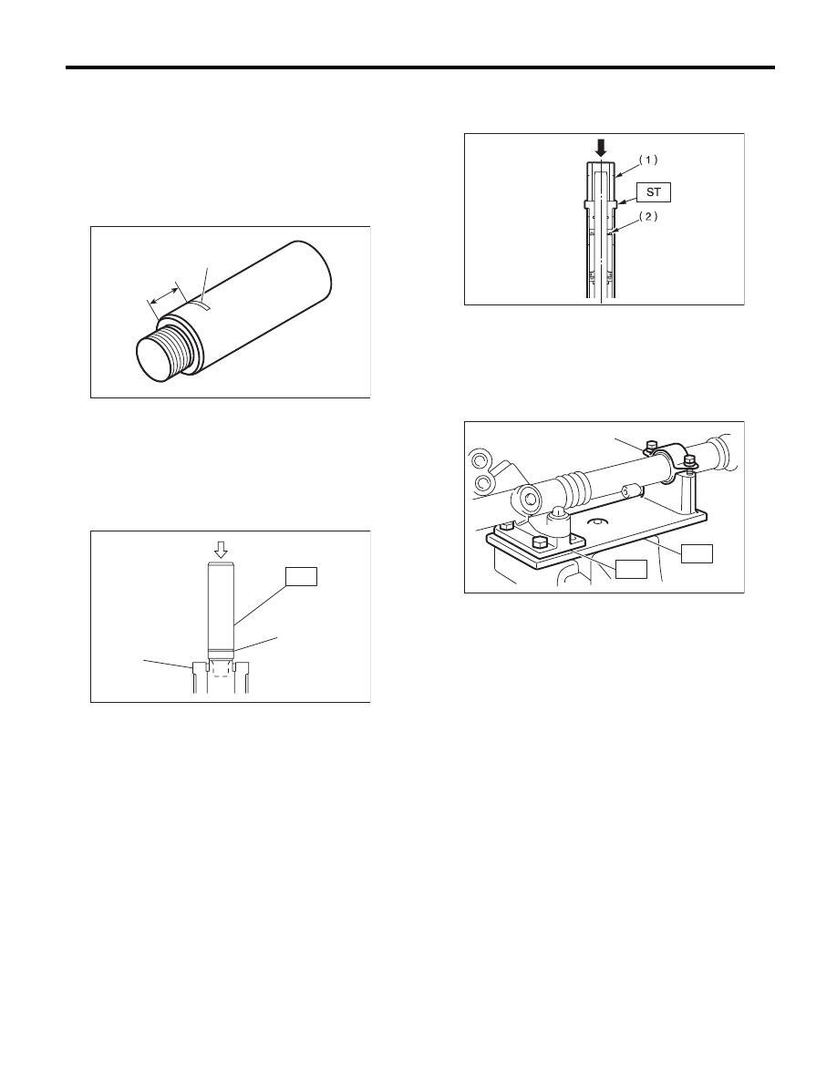
11) Put a mark at the specified position measured
from the end surface of ST, as shown in the figure.

Specified position: 

Except for 2.5 GT-B and 3.0 R-LTD: 

13.5 mm (0.53 in)

2.5 GT-B and 3.0 R-LTD: 

18.9 mm (0.74 in)

ST

34199FE000

INSTALLER & REMOVER

12) Set the ST to the end of rack.
ST

34199FE000

INSTALLER & REMOVER

13) Using a press, press-fit until the mark on ST is
aligned to the end surface of holder.

14) Remove the ST and holder.
15) Insert the outer side oil seal into the rack using
the same procedure as steps 5) and 6).
ST

926390001

COVER & REMOVER

16) Make the ST and the pipe through the rack, and
then press-fit the outer side oil seal using a press.
ST

34199AG010 INSTALLER

17) Secure the gearbox in a vise using ST.
ST1

926200000

STAND

ST2

34199AG000 BOSS D

18) Tighten a new holder.

Tightening torque:

70 N·m (7.1 kgf-m, 51.6 ft-lb)

(1) 13.5 mm (0.53 in) or 18.9 mm (0.74 in)

(2) Put a mark.

(1) Mark

(2) Holder

PS-00851

(1)

(2)

PS-00522

ST

(1)

(2)

(1) Pipe

(2) Outer side oil seal

(1) Clamp

PS-00852

PS-00492

(1)

ST1

ST2

PS-27

Steering Gearbox

POWER ASSISTED SYSTEM (POWER STEERING)

19) Using the ST, crimp so that the diameter of
punch hole is 2 — 2.5 mm (0.08 — 0.10 in) and is
aligned to the position of 2 mm (0.08 in) from gear-
box cylinder end surface.
ST1

34099FA060 PUNCH HOLDER

ST2

34199FE020 BASE

20) Put a vinyl tape around the spline portion and
apply genuine grease to the dust cover and install
to valve assembly.

CAUTION:
Be sure to install the dust cover to groove of
shaft.

21) Apply the genuine grease to the pinion gear
and bearing of valve assembly.

22) Install a new gasket on valve assembly. Insert
the valve assembly into place while facing the rack
teeth toward pinion.

23) Tighten the bolts alternately to secure the valve
assembly.

Tightening torque:

20 N·m (2.0 kgf-m, 14.8 ft-lb)

CAUTION:
Be sure to alternately tighten the bolts.
24) Temporarily install the tie-rod to rack end, and
then operate the rack from lock to lock for two or
three times to make it fit in.

CAUTION:
Operating the rack from lock to lock without in-
stalling tie-rods may damage the oil seal. Al-
ways install the left and right tie-rods.
25) Apply liquid gasket to 1/3 or more of entire pe-
rimeter of adjusting screw thread.

Liquid gasket:

THREE BOND 1141

(A) Holder

(B) 2 mm (0.08 in)

(1) Dust cover

(2) Groove

(A)

(B)

ST1

ST2

ST1

PS-00859

PS-00534

(1)

(2)

 PS-00165

PS-00117

PS-28

Steering Gearbox

POWER ASSISTED SYSTEM (POWER STEERING)

26) Apply a coat of grease to the sliding surface of
sleeve and seating surface of spring, and then in-
sert the sleeve into steering body.
Charge the adjusting screw with grease, and then
insert the spring into adjusting screw. Then install
on the steering body.

27) Tighten the adjusting screw to the specified
torque, then loosen it.

Tightening torque:

25 N·m (2.5 kgf-m, 18.4 ft-lb)

28) Tighten the adjusting screw to the specified
torque, then loosen it 20°.

Tightening torque:

3.9 N·m (0.4 kgf-m, 2.9 ft-lb)

29) Remove the tie-rod.
30) Adjust the adjustment screw until the rotational
resistance of gearbox is within specifications. <Ref.
to PS-35, TURNING RESISTANCE OF GEAR-
BOX, INSPECTION, Steering Gearbox.>
31) Apply liquid gasket to lock nut and install it into
adjusting screw. While holding the adjusting screw
with wrench, tighten the lock nut using ST.

Liquid gasket:

THREE BOND 1141

ST

926230000

SPANNER

Tightening torque (lock nut):

25 N·m (2.5 kgf-m, 18.4 ft-lb)

NOTE:
Hold the adjusting screw with a wrench to prevent it
from turning while tightening lock nut.
32) Extend the rack approx. 40 mm (1.57 in) from
steering body.

33) Install the tie-rod and new lock washer into
rack.

Tightening torque:

90 N·m (9.1 kgf-m, 65.8 ft-lb)

34) Bend the lock washer and crimp it.

CAUTION:
Be careful not to scratch the rack when crimp-
ing lock washer.

(1) Sleeve

(2) Spring

(3) Adjusting screw

PS-00167

(2)

(1)

(3)

(1) Lock washer

(2) Approx. 40 mm (1.57 in)

(1) Lock washer

PS-00439

(2)

(1)

PS-00093

PS-29

Steering Gearbox

POWER ASSISTED SYSTEM (POWER STEERING)

35) Apply a coat of grease to the tie-rod groove,
and then install the boot to the housing.

CAUTION:
Right side boot has groove for identification, be
sure to install the right and left of boot.

NOTE:
Make sure that the boot is installed without unusual
inflation or deflation.

36) Install a new boot band. Using band clamp pli-
ers, crimp it so that the clearance of crimping por-
tion becomes 2 mm (0.079 in) or less.

37) Fix the boot end with small clip.

38) After installing, check that the boot end is in-
stalled to the groove of the tie-rod.

(1) Right side boot

(2) Groove for identification

PS-00524

(2)

(1)

PS-00194

(A) Boot band

(B) 2 mm (0.079 in) or less

(1) Clip

PS-00499

(A)

(B)

PS-00053

(1)


Content   ..  964  965  966  967   ..