Subaru Legacy IV (2008 year). Manual - part 964


  Index      Subaru     Subaru Legacy IV - service repair manual 2008 year


Search            


Content   ..  962  963  964  965   ..


Subaru Legacy IV (2008 year). Manual - part 964


PS-18

Steering Gearbox

POWER ASSISTED SYSTEM (POWER STEERING)

5. Steering Gearbox

A: REMOVAL

1) Set the vehicle on a lift.
2) Disconnect the ground cable from the battery.
3) Loosen the front wheel nuts.
4) Lift up the vehicle, and remove the front wheels.
5) Remove the under cover. <Ref. to EI-26, RE-
MOVAL, Front Under Cover.>
6) Remove the front exhaust pipe assembly. (Non-
turbo model) <Ref. to EX(H4SO)-4, REMOVAL,
Front Exhaust Pipe.>

WARNING:
Be careful not to burn yourself because the ex-
haust pipe is hot.
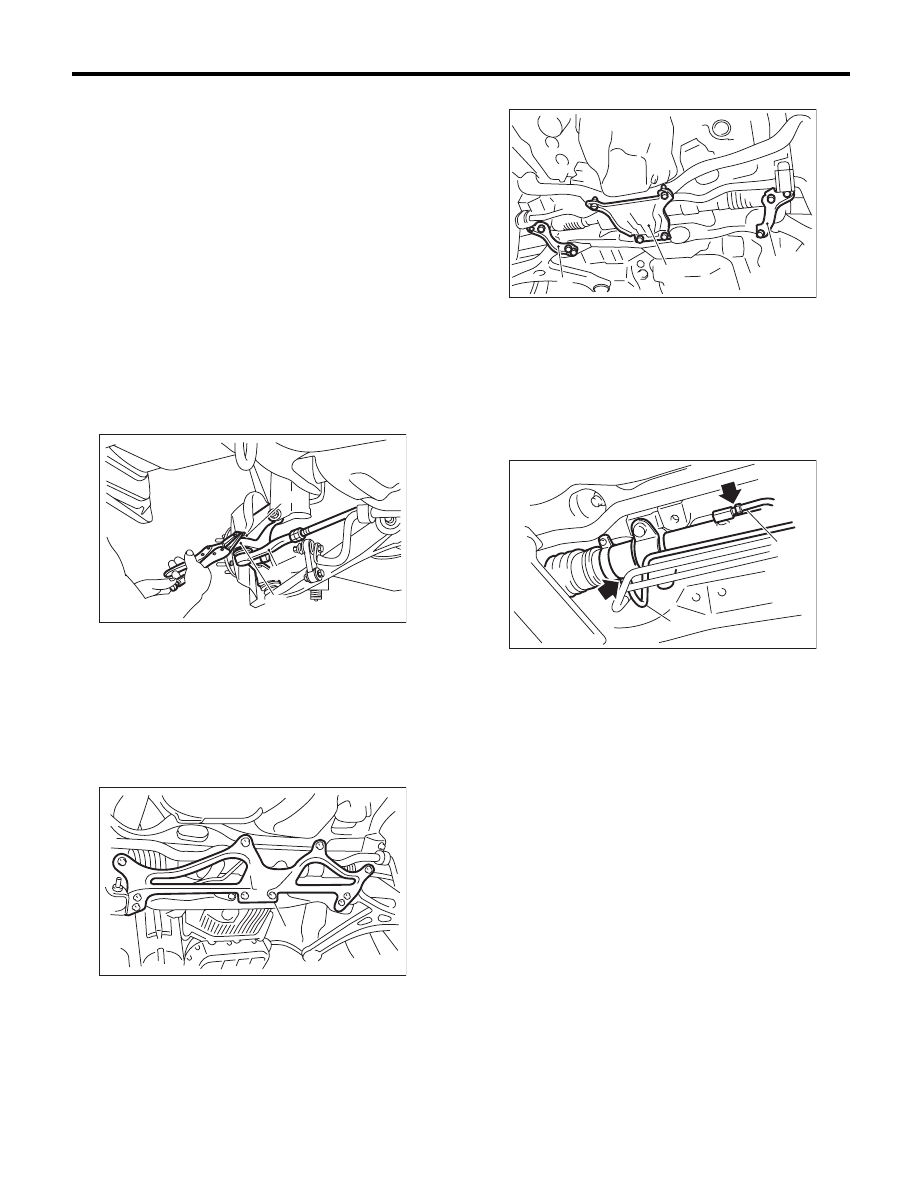
7) After pulling off the cotter pin and removing the
castle nut, use a puller to remove the tie-rod end
from the knuckle arm.

8) Remove the front crossmember support plate,
jack-up plate and front stabilizer. <Ref. to FS-15,
REMOVAL, Front Stabilizer.>
• Large type

• Small type

9) Remove the one pipe joint at the center of the
gearbox, and connect the vinyl hose to the pipe and
the joint. Discharge the fluid by turning the steering
wheel fully clockwise and counterclockwise. Dis-
charge the fluid similarly from other pipes.

10) Remove the universal joint. <Ref. to PS-14,
REMOVAL, Universal Joint.>

(1) Castle nut

(2) Tie-rod end

(3) Knuckle arm

(1) Front crossmember support plate

PS-00043

(1)

(2)

(3)

PS-00445

(1)

(1) Crossmember support plate

(2) Jack-up plate

(1) Pipe A

(2) Pipe B

FS-00105

(2)

(1)

(1)

(2)

PS-00553

(1)

PS-19

Steering Gearbox

POWER ASSISTED SYSTEM (POWER STEERING)

11) Disconnect the pipe C from pressure hose first,
then disconnect pipe D from the return hose.

12) Remove the clamp bolts securing the gearbox
to the crossmember, and remove the clamp.

13) Remove the bolts which secure the gearbox
bracket, and remove the bracket and gearbox.

B: INSTALLATION

1) Insert the gearbox into crossmember, being
careful not to damage gearbox boot.
2) Install the gearbox and bracket. Temporarily
tighten the bolts.

3) Insert bolts through the clamp to temporarily
tighten the gearbox to the crossmember bracket.

4) Tighten the bolts temporarily holding the gear-
box clamp and bracket together to the specified
torque.

Tightening torque:

60 N·m (6.1 kgf-m, 44.1 ft-lb)

(1) Pipe C

(2) Pipe D

(3) Pressure hose

(4) Return hose

(1) Clamp

PS-00538

(4)

(3)

(2)

(1)

PS-00554

(1)

(1) Bracket

(1) Bracket

(1) Clamp

(1)

PS-00555

(1)

PS-00555

PS-00554

(1)

PS-20

Steering Gearbox

POWER ASSISTED SYSTEM (POWER STEERING)

5) Connect pipe D to the return hose, then connect
pipe C to the pressure hose.

Tightening torque:

15 N·m (1.5 kgf-m, 10.8 ft-lb)

6) Install the universal joint. <Ref. to PS-14, IN-
STALLATION, Universal Joint.>
7) Connect the tie-rod end and knuckle arm, and
tighten with castle nut.

Castle nut tightening torque:

27 N·m (2.75 kgf-m, 19.9 ft-lb)

CAUTION:
When connecting, do not hit the cap at the bot-
tom of tie-rod end with hammer.

8) After tightening the castle nut to the specified
tightening torque, tighten it further within 60° until
the cotter pin hole is aligned with slot in the nut. Fit
the cotter pin into the nut, and then bend the pin to
lock.

9) Install the front stabilizer. <Ref. to FS-15, IN-
STALLATION, Front Stabilizer.>
10) Install the front crossmember support plate and
jack-up plate.
11) Install the front exhaust pipe assembly. (Non-
turbo model) <Ref. to EX(H4SO)-5, INSTALLA-
TION, Front Exhaust Pipe.>
12) Install the under cover. <Ref. to EI-26, INSTAL-
LATION, Front Under Cover.>
13) Install the front wheels.
14) Tighten the wheel nuts to the specified torque.

Tightening torque:

120 N·m (12.2 kgf-m, 88.5 ft-lb)

15) Lower the vehicle.
16) Remove the steering wheel. <Ref. to PS-13,
REMOVAL, Steering Wheel.>
17) Align the center position of the roll connector.
<Ref. to AB-25, ADJUSTMENT, Roll Connector.>
18) Install the steering wheel. <Ref. to PS-13, IN-
STALLATION, Steering Wheel.>
19) Connect the ground cable to battery.
20) Pour fluid into the oil tank, and bleed air. <Ref.
to PS-53, Power Steering Fluid.>
21) Check for fluid leaks.
22) Check the fluid level in oil tank.

(1) Pipe C

(2) Pipe D

(3) Pressure hose

(4) Return hose

PS-00538

(4)

(3)

(2)

(1)

(A) Cotter pin

(B) Castle nut

(C) Tie-rod end

DS-00042

(C)

(B)

(A)

PS-21

Steering Gearbox

POWER ASSISTED SYSTEM (POWER STEERING)

23) After adjusting toe-in and steering angle, tight-
en the lock nut on tie-rod end.

Tightening torque:

85 N·m (8.7 kgf-m, 62.7 ft-lb)

NOTE:
When adjusting toe-in, hold the boot as shown to
prevent it from being rotated or twisted. If it be-
comes twisted, straighten it.

C: DISASSEMBLY

1. RACK HOUSING ASSEMBLY

1) Disconnect the four pipes from gearbox.

NOTE:
Remove the pipes C and D, which are fixed to
clamp plate, as a unit.
2) Secure the gearbox removed from vehicle in a
vise using ST.
ST1

926200000

STAND

ST2

34199AG000 BOSS D

CAUTION:
Secure the gearbox in a vise using ST as shown
in the figure. Do not secure the gearbox without
this ST.

3) Remove the tie-rod end and lock nut from gear-
box.

4) Remove the small clip from the boot using pliers,
and then move the boot to tie-rod end side.

5) Using a flat tip screwdriver, remove the band
from boot.

NOTE:
Replace the boot if there is damage, cracks or de-
terioration.

6) Using the ST, loosen the lock nut.
ST

926230000

SPANNER

(1) Clamp

PS-00051

PS-00492

(1)

ST1

ST2

(1) Clip

(1) Band

(1) Lock nut

PS-00053

(1)

PS-00509

(1)

PS-00494

ST

(1)


Content   ..  962  963  964  965   ..