Subaru Legacy IV (2008 year). Manual - part 920
VDC-18
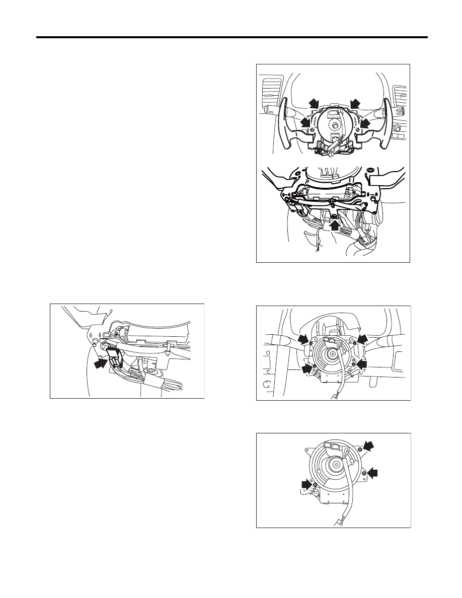
Steering Angle Sensor
VEHICLE DYNAMICS CONTROL (VDC)
6. Steering Angle Sensor
A: REPLACEMENT
CAUTION:
• Do not perform the removal except when the
replacement.
• When replacing three times or more, replace
the combination switch as assembly to protect
the threads.
1) Set the steering wheel in a straight-ahead posi-
tion.
2) Disconnect the ground cable from battery.
3) Remove the airbag module.
<Ref. to AB-14, REMOVAL, Driver’s Airbag Mod-
ule.>
WARNING:
Always refer to “Airbag System” when perform-
ing the airbag module repair service.
<Ref. to AB-4, CAUTION, General Description.>
4) Remove the steering wheel.
<Ref. to PS-13, REMOVAL, Steering Wheel.>
5) Remove the screws and remove the steering
column lower cover.
6) Remove the two screws securing the steering
column upper cover.
7) Disconnect the connector of paddle shift assem-
bly. (Model with paddle shift)
8) Remove the paddle shift assembly. (Model with
paddle shift)
9) Disconnect the connector of roll connector and
steering angle sensor.
10) Remove the screws which secure the roll con-
nector to steering column.
11) Remove the vinyl tape binding the harness,
and remove the steering angle sensor from roll
connector.
CS-00728
CS-00729
VDC00207
VDC00208