Subaru Legacy IV (2008 year). Manual - part 918
VDC-10
VDC Control Module and Hydraulic Control Unit (VDCCM&H/U)
VEHICLE DYNAMICS CONTROL (VDC)
D: REPLACEMENT
CAUTION:
• Because the pressure sensor built into the H/
U is easily damaged by static electricity, start
the operation after performing static electricity
measures.
• Be careful not to touch the sensors in the H/U
to prevent damage.
• Because the seal of the VDCCM cannot be re-
placed, do not pull or peel it by lifting it up.
• Because the screw of the H/U will become
slightly worn in every replacement procedure, 5
times is the maximum number of times for re-
placement. If a problem is found such as not
being able to torque the screw to specifications
even before 5 replacement operations are per-
formed, replace the H/U body.
• When installing the VDCCM, always use new
screws.
• When the sealing surface of the VDCCM or H/
U is dirty or damaged and it cannot be cleaned
or repaired, replace with a new part.
1) Remove the VDCCM&H/U. <Ref. to VDC-7, RE-
MOVAL, VDC Control Module and Hydraulic Con-
trol Unit (VDCCM&H/U).>
2) To prevent entry of foreign objects and brake flu-
id leakage, plug the oil pressure port of the VDC-
CM&H/U using a screw plug, etc.
3) Set the pump motor section of the removed VD-
CCM&H/U face down on a vise.
NOTE:
Before securing a part in a vise, place cushioning
material such as wood blocks, aluminum plate or
cloth between the part and the vise.
4) Using TORX
®
bit E5, remove the four screws of
VDCCM.
NOTE:
These screws cannot be reused.
5) Slowly pull out the VDCCM upward from the H/U.
NOTE:
To prevent damaging of coil section, remove the
VDCCM straight up from H/U without twisting.
6) Make sure there is no dirt or damage on the seal-
ing surface of the H/U.
CAUTION:
• Do not clean the VDCCM&H/U by applying
compressed air.
• Even if damage is found on the H/U seal, do
not attempt repair by filing or with a metal
scraper. To remove the seal residue, always
use a plastic scraper. Do not use chemical such
as paint thinner, etc., to clean.
7) Position the coil of the new VDCCM to align with
the H/U valve.
8) To prevent deformation of the VDCCM housing
cover, hold the corner of VDCCM and install it to
the H/U without tilting.
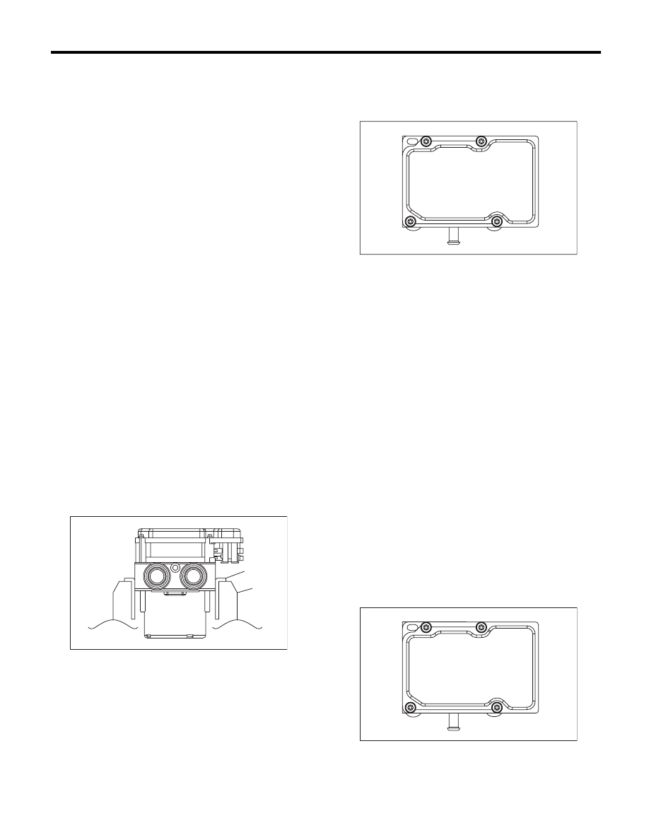
9) Using a TORX
®
bit E5, attach/tighten new
screws in the order of (1) through (4).
CAUTION:
Always use new screws.
Tightening torque:
1.5 N·m (0.15 kgf-m, 1.1 ft-lb)
10) Check that there is no foreign matter in mating
surface between the VDCCM&H/U.
(1) Aluminum plate, etc.
(2) Vise
ABS00430
(1)
(2)
ABS00431
ABS00432
(4)
(2)
(1)
(3)