Subaru Legacy IV (2008 year). Manual - part 907
ABS(diag)-27
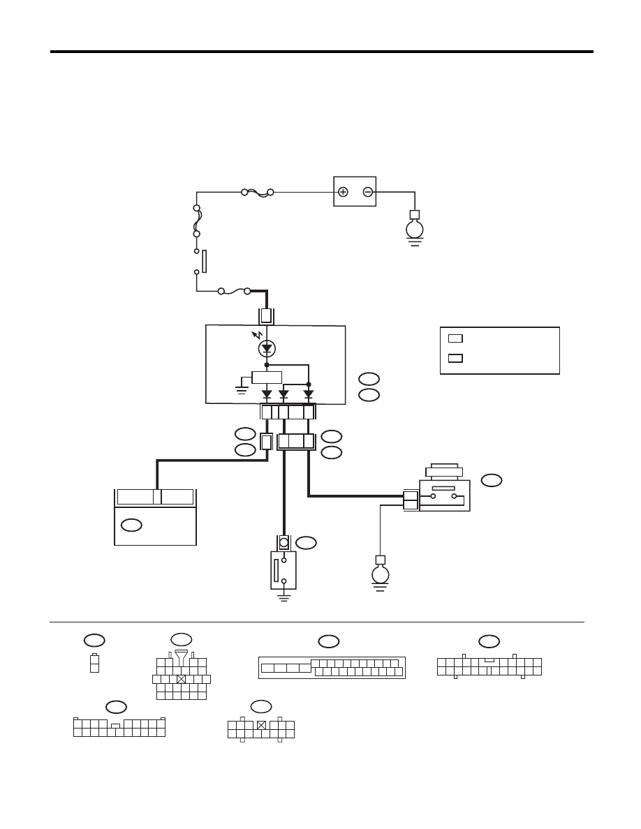
ABS Warning Light / Brake Warning Light Illumination Pattern
ABS (DIAGNOSTICS)
D: BRAKE WARNING LIGHT DOES NOT GO OFF
DETECTING CONDITION:
• Brake warning light circuit is shorted.
• Defective sensor/connector
TROUBLE SYMPTOM:
After starting the engine, the brake warning light remains lit though the parking lever is released.
WIRING DIAGRAM:
B301
B16
1
2
1 2 3 4 5 6 7 8 9 10 11
16 17 18 19 20 21 22 23 24 25 26
13
12
15
14
i10
2
1
3 4
6 7 8 9 10
22
21
20
19
18
17
16
15
14
13
12
11
5
A:
B:
E
MAIN SBF
SBF-6
E
No.5
8
B301
B36
B16
i1
B38
i3
B404
i10
A:
i11
B:
ABSCM & H/U
A3
A7
20
16
15
1
2
1
*
2
*
2
*
B38
1 2 3 4
5 6 7 8 9
10 11 12 13 14 15 16 17 18 19 20
i1
5 6 7 8
2
1
9
4
3
10
24
22
23
25
27
26
28
11 12 13
14 15 16
17 18 19 20 21
ABS01070
1
*
1 2 3
4 5 6
7 8 9 10 11 12 13 14
i11
BATTERY
IGNITION
SWITCH
COMBINATION
METER
PARKING BRAKE
FLUID LEVEL
WARNING LIGHT
BRAKE FLUID
LEVEL SWITCH
PARKING
SWITCH
REVERSE
CIRCUIT
: NORMAL METER
METER WITH MID
: A8
: A4
: NORMAL METER
METER WITH MID
: B10
: A8