Subaru Legacy IV (2008 year). Manual - part 906
ABS(diag)-23
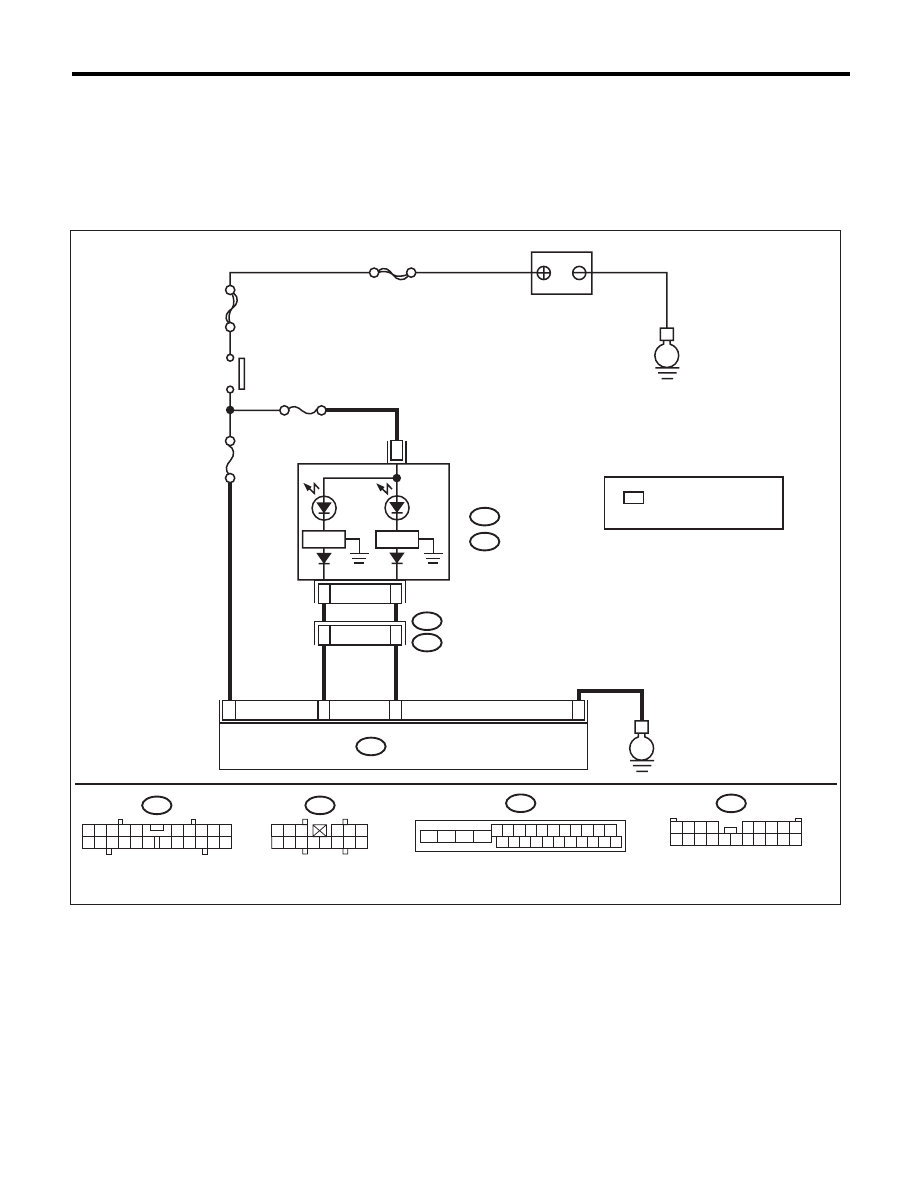
ABS Warning Light / Brake Warning Light Illumination Pattern
ABS (DIAGNOSTICS)
B: ABS WARNING LIGHT DOES NOT COME ON
DETECTING CONDITION:
• Defective combination meter
• Defective harness
TROUBLE SYMPTOM:
When the ignition switch is turned to ON (engine OFF), ABS warning light does not illuminate.
WIRING DIAGRAM:
MAIN SBF
SBF-6
No.5
No.33
A:
i10
B:
i11
E
E
B301
18
15
22
ABSCM & H/U
A7
8
i3
B38
A3
1 2 3 4 5 6 7 8 9 10 11
16 17 18 19 20 21 22 23 24 25 26
13
12
15
14
i10
2
1
3 4
6 7 8 9 10
22
21
20
19
18
17
16
15
14
13
12
11
5
A:
B301
B38
1
*
20
9
1
*
i11
B:
2
1
3
4 5 6
14
13
12
11
10
9
8
7
ABS01069
1 2 3 4
5 6 7 8 9
10 11 12 13 14 15 16 17 18 19 20
BATTERY
IGNITION
SWITCH
COMBINATION
METER
: NORMAL METER
METER WITH MID
REVERSE
CIRCUIT
REVERSE
CIRCUIT
BRAKE
W
ARNING
LIGHT
ABS
W
ARNING
LIGHT
: A5
: B5