Subaru Legacy IV (2008 year). Manual - part 890
DS-5
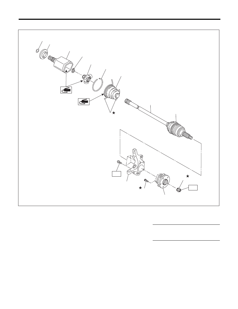
General Description
DRIVE SHAFT SYSTEM
2. FRONT AXLE
(1)
Circlip
(7)
Boot band
(13)
Front hub unit bearing
(2)
Baffle plate
(8)
Boot (PTJ)
(14)
Axle nut
(3)
Outer race (PTJ)
(9)
Boot (EBJ)
(4)
Snap ring
(10)
EBJ shaft ASSY
Tightening torque:N·m (kgf-m, ft-lb)
(5)
Trunnion
(11)
Housing
T1: 220 (22.4, 162)
(6)
Snap ring
(12)
Hub bolt
T2: 65 (6.6, 47.9)
(3)
(2)
(1)
(13)
(4)
(5)
(14)
(9)
(10)
(12)
(7)
(6)
(11)
T2
T1
(8)
DS-00232