Subaru Legacy IV (2008 year). Manual - part 821
6MT-97
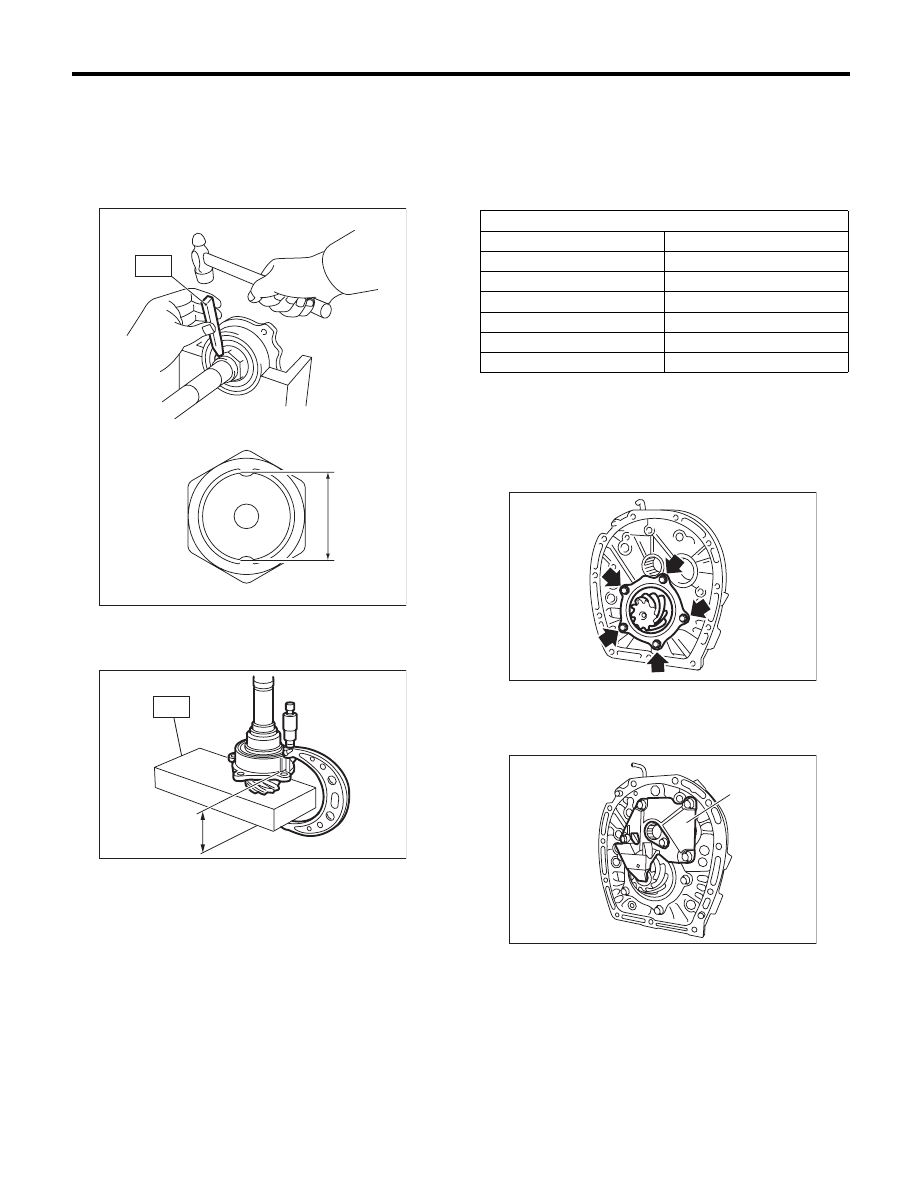
Drive Pinion Shaft Assembly
MANUAL TRANSMISSION AND DIFFERENTIAL
7) Using the ST, crimp the lock nut in 2 locations,
with dimensions within A 37
r0.5 mm (1.46r0.02
in).
ST
18670AA000
PUNCH
NOTE:
Do not damage the crimp area of the lock nut.
8) Using the ST, measure drive pinion measure-
ment B.
ST
398643600
GAUGE
9) Calculate from the calculation below to select 1
or 2 drive pinion shims from the following table.
6.5
r0.0625 mm – (B – A) [0.26r0.0025 in – (B – A)]
NOTE:
A: Measurement value in step 1)
B: Measurement value in step 8)
10) Apply transmission gear oil to the side face of
the taper roller bearing, and attach the drive pinion
shaft and the selected shims to the adapter plate.
Tightening torque:
54 N·m (5.5 kgf-m, 40 ft-lb)
11) Install the oil guide A.
Tightening torque:
18 N·m (1.8 kgf-m, 13.3 ft-lb)
MT-00649
A
ST
MT-00650
B
ST
Drive pinion shim
Part No.
Thickness mm (in)
32295AA270
0.15 (0.0059)
32295AA280
0.175 (0.0069)
32295AA290
0.20 (0.0079)
32295AA300
0.225 (0.0089)
32295AA310
0.25 (0.0098)
32295AA320
0.275 (0.0108)
(A) Oil guide A
MT-00642
MT-01624
(A)