Subaru Legacy IV (2008 year). Manual - part 819
6MT-89
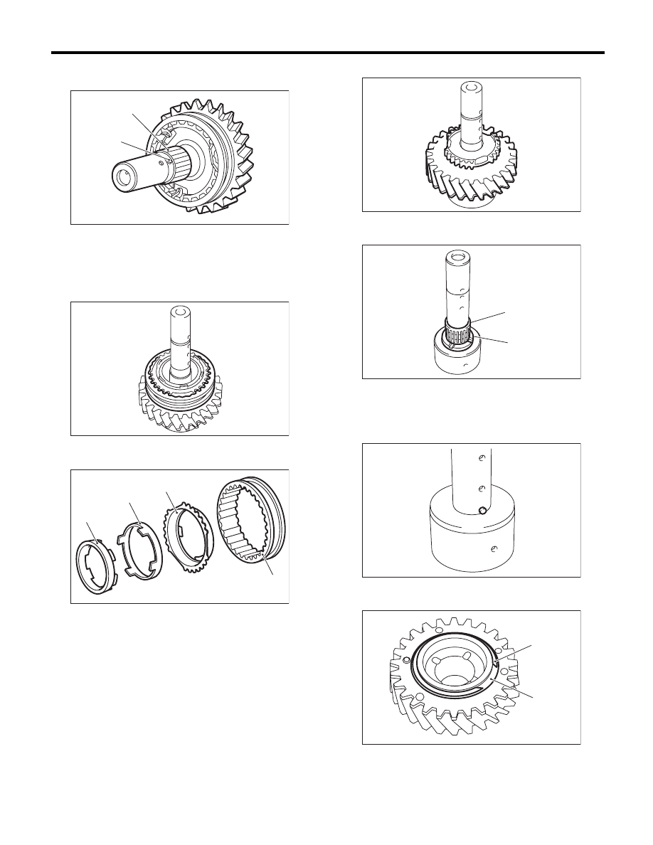
Reverse Idler Gear Assembly
MANUAL TRANSMISSION AND DIFFERENTIAL
4) Remove the knock pin and reverse idler gear
needle bearing.
5) Remove the collar.
6) Remove the reverse sleeve.
7) Remove the outer baulk ring, reverse synchro
cone and inner baulk ring from the reverse sleeve.
8) Remove reverse idler gear No. 2.
9) Remove the counter high & low washer and nee-
dle bearing.
10) Remove the knock pin.
11) Remove the snap ring and friction plate from
reverse gear.
(A) Knock pin
(B) Reverse idler gear needle bearing
(A) Reverse sleeve
(B) Outer baulk ring
(C) Reverse synchro cone
(D) Inner baulk ring
MT-00620
(A)
(B)
MT-00622
MT-01507
(A)
(B)
(C)
(D)
(A) Needle bearing
(B) Counter high and low washer
(A) Snap ring
(B) Friction plate
MT-00624
MT-00625
(A)
(B)
MT-00626
MT-00627
(B)
(A)