Subaru Legacy IV (2008 year). Manual - part 808
6MT-45
Extension Case
MANUAL TRANSMISSION AND DIFFERENTIAL
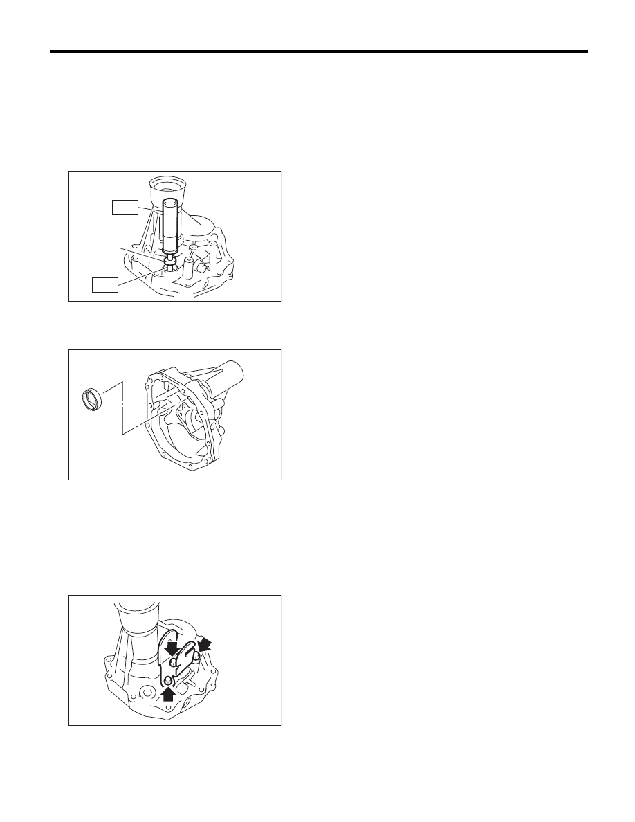
D: ASSEMBLY
1) Install the reverse check system. <Ref. to 6MT-
51, INSTALLATION, Reverse Check System.>
2) Install the extension case oil seal. <Ref. to 6MT-
28, REPLACEMENT, Oil Seal.>
3) Install a shifter arm oil seal using the ST.
ST1
18657AA000
INSTALLER
ST2
18671AA000
OIL SEAL GUIDE
4) Install the oil plate.
5) Select the thrust washer of the bearing, and at-
tach to the extension case. <Ref. to 6MT-46, AD-
JUSTMENT, Extension Case.>
6) Apply a thin coat of oil to the outer surface of the
bearing cone, and attach to the extension case.
7) Install the shift bracket.
Tightening torque:
25 N·m (2.5 kgf-m, 18.4 ft-lb)
8) Attach the oil guide and the transfer driven gear.
<Ref. to 6MT-53, INSTALLATION, Transfer Drive
Gear.>
E: INSPECTION
1) Check to make sure there is no damage or
cracks on the extension case. If damage or crack-
ing is found, replace the extension case.
2) Inspect for oil leaks at the extension case and
transmission case oil seals and mating surfaces. If
there are oil leaks, replace the oil seal and liquid
gasket.
(A) Oil seal
MT-00482
(A)
ST1
ST2
MT-00483
MT-00478