Subaru Legacy IV (2008 year). Manual - part 795


  Index      Subaru     Subaru Legacy IV - service repair manual 2008 year


Search            


Content   ..  793  794  795  796   ..


Subaru Legacy IV (2008 year). Manual - part 795


5MT-76

Front Differential Assembly

MANUAL TRANSMISSION AND DIFFERENTIAL

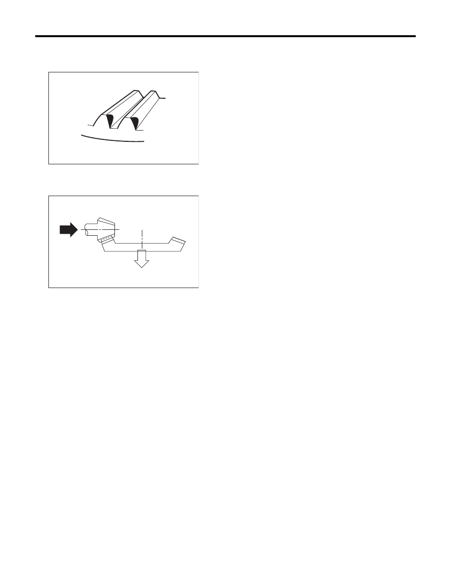
• Heel contact (outside end contact)
Check item: Teeth contact area is too small.
Contact pattern

Corrective action: Reduce the thickness of the
drive pinion shim according to the procedure for
moving the drive pinion away from the driven gear.

AT-00211

AT-00212

5MT-77

Reverse Idler Gear

MANUAL TRANSMISSION AND DIFFERENTIAL

18.Reverse Idler Gear

A: REMOVAL

1) Remove the manual transmission assembly
from the vehicle. <Ref. to 5MT-24, REMOVAL,
Manual Transmission Assembly.>
2) Remove the back-up light switch neutral position
switch. <Ref. to 5MT-35, REMOVAL, Switches and
Harness.>
3) Remove the transfer case together with the ex-
tension case assembly. <Ref. to 5MT-38, REMOV-
AL, Transfer Case and Extension Case
Assembly.>
4) Remove the transmission case. <Ref. to 5MT-
51, REMOVAL, Transmission Case.>
5) Remove the drive pinion shaft assembly. <Ref.
to 5MT-60, REMOVAL, Drive Pinion Shaft Assem-
bly.>
6) Remove the main shaft assembly for single-
range. <Ref. to 5MT-54, REMOVAL, Main Shaft
Assembly for Single-Range.>
7) Remove the front differential assembly. <Ref. to
5MT-69, REMOVAL, Front Differential Assembly.>
8) Remove the shifter forks and rods. <Ref. to 5MT-
79, REMOVAL, Shifter Fork and Rod.>
9) Pull out the straight pin, and remove the reverse
idler gear shaft, washer, reverse idler gear and
washer.

10) Remove the reverse shifter lever.

B: INSTALLATION

1) Install the reverse shifter lever, washer, reverse
idler gear, washer and reverse idler gear shaft, and
secure them with the straight pin.

NOTE:
Be sure to install the reverse idler gear shaft from
rear side.

2) Check and adjust clearance between the re-
verse idler gear and the transmission case wall sur-
face. <Ref. to 5MT-77, INSTALLATION, Reverse
Idler Gear.> <Ref. to 5MT-78, ADJUSTMENT, Re-
verse Idler Gear.>
3) Install the shifter forks and rods. <Ref. to 5MT-
80, INSTALLATION, Shifter Fork and Rod.>
4) Install the front differential assembly. <Ref. to
5MT-69, INSTALLATION, Front Differential As-
sembly.>
5) Install the main shaft assembly for single-range.
<Ref. to 5MT-54, INSTALLATION, Main Shaft As-
sembly for Single-Range.>
6) Install the drive pinion shaft assembly. <Ref. to
5MT-60, INSTALLATION, Drive Pinion Shaft As-
sembly.>
7) Install the transmission case. <Ref. to 5MT-52,
INSTALLATION, Transmission Case.>
8) Install the transfer case together with the exten-
sion case assembly. <Ref. to 5MT-38, INSTALLA-
TION, Transfer Case and Extension Case
Assembly.>
9) Install the back-up light switch neutral position
switch. <Ref. to 5MT-35, INSTALLATION, Switch-
es and Harness.>
10) Install the manual transmission assembly to the
vehicle. <Ref. to 5MT-27, INSTALLATION, Manual
Transmission Assembly.>

(A) Straight pin

(B) Reverse idler gear shaft

(C) Reverse idler gear

(D) Washer

(E) Washer

(F) Reverse shifter lever

MT-01565

(A)

(B)

(C)

(D)

(F)

(E)

(A) Straight pin

(B) Reverse idler gear shaft

(C) Reverse idler gear

(D) Washer

(E) Washer

(F) Reverse shifter lever

MT-01565

(A)

(B)

(C)

(D)

(F)

(E)

5MT-78

Reverse Idler Gear

MANUAL TRANSMISSION AND DIFFERENTIAL

C: INSPECTION

1) Move the reverse shifter rod toward the reverse
side. Check the clearance between the reverse
idler gear and the timing case wall surface.
If out of specification, select an appropriate reverse
shifter lever and adjust.

Clearance A:

6.0 — 7.5 mm (0.236 — 0.295 in)

2) After installing a suitable reverse shifter lever,
shift into neutral. Check the clearance between the
reverse idler gear and the timing case wall surface.
If out of specification, select the appropriate washer
and adjust.

Clearance:

0 — 0.5 mm (0 — 0.020 in)

3) Check the reverse idler gear and shaft for dam-
age. Replace if damaged.

D: ADJUSTMENT

1) Select the appropriate reverse shifter lever from
the table below, and adjust until the clearance be-
tween the reverse idler gear and transmission case
wall is within specification.

Clearance A:

6.0 — 7.5 mm (0.236 — 0.295 in)

2) Select the appropriate washer from the table be-
low, and adjust until the clearance between the re-
verse idler gear and transmission case wall is
within specification.

Clearance:

0 — 0.5 mm (0 — 0.020 in)

A Measured value

MT-00305

A

MT-00306

A Measured value

Reverse shifter lever

Part number

Mark

Remarks

32820AA070

7

Far from case wall

32820AA080

8

Standard

32820AA090

9

Closer to case wall

Washer

Part number

Thickness mm (in)

803020151

0.4 (0.016)

803020152

1.1 (0.043)

803020153

1.5 (0.059)

803020154

1.9 (0.075)

803020155

2.3 (0.091)

MT-00305

A

MT-00306

5MT-79

Shifter Fork and Rod

MANUAL TRANSMISSION AND DIFFERENTIAL

19.Shifter Fork and Rod

A: REMOVAL

1) Remove the manual transmission assembly
from the vehicle. <Ref. to 5MT-24, REMOVAL,
Manual Transmission Assembly.>
2) Remove the back-up light switch neutral position
switch. <Ref. to 5MT-35, REMOVAL, Switches and
Harness.>
3) Remove the transfer case together with the ex-
tension case assembly. <Ref. to 5MT-38, REMOV-
AL, Transfer Case and Extension Case
Assembly.>
4) Remove the transmission case. <Ref. to 5MT-
51, REMOVAL, Transmission Case.>
5) Remove the drive pinion shaft assembly. <Ref.
to 5MT-60, REMOVAL, Drive Pinion Shaft Assem-
bly.>
6) Remove the main shaft assembly for single-
range. <Ref. to 5MT-54, REMOVAL, Main Shaft
Assembly for Single-Range.>
7) Remove the front differential assembly. <Ref. to
5MT-69, REMOVAL, Front Differential Assembly.>
8) Drive out the straight pin by tapping with the ST,
and pull out the 5th shifter fork.
ST

398791700

STRAIGHT PIN REMOVER 2

9) Remove the plugs, springs and check balls.

10) Drive out the straight pin by tapping with the
ST, and pull out the 3rd – 4th fork rod and shifter
fork.

NOTE:
When removing the rod, keep other rods in neutral.
Also, when pulling out the straight pin, remove it to-
ward the inside of case so that it does not hit
against the case.
ST

398791700

STRAIGHT PIN REMOVER 2

11) Drive out the straight pin by tapping with the
ST, and pull out the 1st – 2nd fork rod and shifter
fork.
ST

398791700

STRAIGHT PIN REMOVER 2

12) Remove the snap ring (outer), and pull out the
reverse fork rod from reverse fork rod arm. Then
take out the ball, spring and interlock plunger from
the rod.
And then remove the rod.

NOTE:
When pulling out the reverse fork rod arm, be care-
ful not to let the ball pop out of arm.
13) Remove the reverse shifter lever.

(A) Straight pin

(B) 5th shifter fork

MT-00309

( A )

( B )

(A) Straight pin

(B) 3rd-4th fork rod

(C) Shifter fork

MT-00994

(A)

(B)

(C)


Content   ..  793  794  795  796   ..