Subaru Legacy IV (2008 year). Manual - part 792


  Index      Subaru     Subaru Legacy IV - service repair manual 2008 year


Search            


Content   ..  790  791  792  793   ..


Subaru Legacy IV (2008 year). Manual - part 792


5MT-64

Drive Pinion Shaft Assembly

MANUAL TRANSMISSION AND DIFFERENTIAL

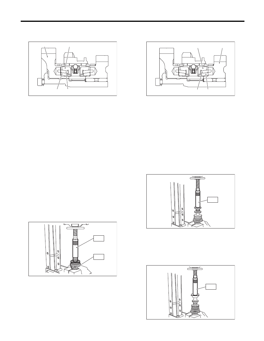
3) Install the 1st driven gear, inner baulk ring, syn-
chro cone and outer baulk ring, and gear & hub as-
sembly onto driven shaft.

NOTE:
• Take care to install the gear & hub assembly in
proper direction.
• Align the baulk ring and gear & hub assembly
with the key groove.
4) Install the 2nd driven gear bushing onto driven
shaft using ST1, ST2 and a press.

CAUTION:
Do not apply pressure in excess of 10 kN (1 ton,
1.1 US ton, 1.0 Imp ton).

NOTE:
• Attach a cloth to the end of the driven shaft to
prevent damage.
• When press fitting, align the oil holes of the shaft
and bushing
ST1

499277200

INSTALLER

ST2

499587000

INSTALLER

5) Install the 2nd driven gear, inner baulk ring, syn-
chro cone and outer baulk ring, and insert them
onto driven shaft.

6) After installing key on driven shaft, install the
3rd-4th driven gear using an ST and a press.

CAUTION:
Do not apply pressure in excess of 10 kN (1 ton,
1.1 US ton, 1.0 Imp ton).

NOTE:
Align the groove in baulk ring with the insert.
ST

499277200

INSTALLER

7) Install a set of roller bearings onto the driven
shaft using ST and a press.

CAUTION:
Do not apply pressure in excess of 10 kN (1 ton,
1.1 US ton, 1.0 Imp ton).
ST

499277200

INSTALLER

(A) 1st driven gear

(B) Inner baulk ring

(C) Synchro cone

(D) Outer baulk ring

(D)

(C)

(B)

(A)

MT-01634

MT-00253

ST1

ST2

(A) 2nd driven gear

(B) Inner baulk ring

(C) Synchro cone

(D) Outer baulk ring

(A)

(B)

(C)

(D)

MT-01633

MT-00255

ST

MT-00256

ST

5MT-65

Drive Pinion Shaft Assembly

MANUAL TRANSMISSION AND DIFFERENTIAL

8) Position the woodruff key in groove of the rear of
driven shaft. Install the 5th driven gear onto driven
shaft using ST and a press.

CAUTION:
Do not apply pressure in excess of 10 kN (1 ton,
1.1 US ton, 1.0 Imp ton).
ST

499277200

INSTALLER

9) Install the lock washer. Tighten the lock nuts to
the specified torque using ST1 and ST2.
ST1

499987300

SOCKET WRENCH (50)

ST2

899884100

HOLDER

Tightening torque:

260 N·m (26.5 kgf-m, 191.8 ft-lb)

NOTE:
• Crimp the locknut in 2 locations.
• Using a spring scale, check that starting torque
of the roller bearing is 0.1 to 1.5 N (0.01 to 0.15 kgf,
0.02 to 0.34 lbf).

10) Install the roller bearing onto drive pinion.

NOTE:
When installing the roller bearing, note its direc-
tions (front and rear) because the knock pin hole of
outer race is offset.

11) Install the washer using ST1, ST2 and a press.

CAUTION:
Do not apply pressure in excess of 10 kN (1 ton,
1.1 US ton, 1.0 Imp ton).
ST1

499277100

BUSHING 1-2 INSTALLER

ST2

499277200

INSTALLER

12) Install the thrust bearing and needle bearing.
Install the driven shaft assembly.

MT-00257

ST

MT-01815

ST2

ST1

MT-00259

(A) Roller bearing

(B) Knock pin hole

(A) Washer

MT-00260

(A)

(B)

MT-00261

(A)

ST1

ST2

MT-00262

5MT-66

Drive Pinion Shaft Assembly

MANUAL TRANSMISSION AND DIFFERENTIAL

13) Install the drive pinion collar, needle bearing,
adjusting washer No. 2, thrust bearing, adjusting
washer No. 1 and differential bevel gear sleeve in
this order.

NOTE:
Be careful to install the spacer in the proper direc-
tion.

14) Adjust the thrust bearing preload. <Ref. to
5MT-67, THRUST BEARING PRELOAD, AD-
JUSTMENT, Drive Pinion Shaft Assembly.>

E: INSPECTION

Disassembled parts should be washed clean first
with cleaning solvent and then inspected carefully.
1) Bearing
Replace the bearings in the following cases.
• When the bearing balls, outer races and inner
races are broken or rusty.
• When the bearing is worn.
• When the bearings fail to turn smoothly or emit
noise in rotation after gear oil lubrication.
• The ball bearing on the rear side of the drive pin-
ion shaft should be checked for smooth rotation be-
fore the drive pinion assembly is disassembled. In
this case, because a preload is working on the
bearing, its rotation feels like it is slightly dragging
unlike other bearings.

• When the bearing has other problems.
2) Bushing (each gear)
Replace the bushing in following cases.
• When the sliding surface is damaged or abnor-
mally worn.
• When the inner wall is abnormally worn.
3) Gear
Replace the bearings in the following cases.
• Replace gear with new part if its tooth surfaces
are broken, damaged or excessively worn.
• Correct or replace if the cone that contacts the
baulk ring is rough or damaged.
• Correct or replace if the inner surface or end face
is damaged.

(A) Driven shaft

(B) Drive pinion shaft

(C) Drive pinion collar

(D) Needle bearing (25 × 30 × 20)

(E) Adjusting washer No. 2 (25 × 36 × 4)

(F) Thrust bearing (25 × 37.5 × 3)

(G) Adjusting washer No. 1 (25 × 36 × t)

(H) Differential bevel gear sleeve

MT-00263

(A) (B)

(C) (D) (E) (F) (G)

(H)

(A) Drive pinion shaft

(B) Ball bearing

MT-00264

(A)

(B)

5MT-67

Drive Pinion Shaft Assembly

MANUAL TRANSMISSION AND DIFFERENTIAL

4) Baulk ring
Replace the ring in following cases:
• When the inner surface and end face are dam-
aged.
• When the ring inner surface is abnormally or par-
tially worn down.
• If the gap between the end faces of the ring and
the gear splined part is excessively small, check
the clearance (A) while pressing the ring against
the cone.

Clearance (A):

0.5 mm (0.020 in) or more

• When the contact surface of the synchronizer
ring insert section is scratched or abnormally worn.
5) Ball detent
Replace the ball detent if deformed, excessively
worn or defective in any way.

6) Oil seal
Replace the oil seal if the lip is deformed, hard-
ened, worn or defective in any way.
7) O-ring
Replace the O-ring if the sealing face is deformed,
hardened, damaged, worn or defective in any way.

F: ADJUSTMENT

1. THRUST BEARING PRELOAD

1) Select a suitable adjusting washer No. 1 to so
that dimension (H) will be zero in a visual check.
Position the washer (18.3 × 30 × 4) and lock wash-
er (18 × 30 × 2) and install lock nut. (18 × 13.5)

2) Using the ST1, ST2 and ST3, tighten the new
lock nut to the specified torque.
ST1

899884100

HOLDER

ST2

498427100

STOPPER

ST3

899988608

SOCKET WRENCH (27)

Tightening torque:

120 N·m (12.2 kgf-m, 88.5 ft-lb)

(A) Measured value

(A) Ball detent

(A)

MT-01674

MT-01640

(A)

MT-00267

(H)

MT-00268

ST1

ST2

ST3


Content   ..  790  791  792  793   ..