Subaru Legacy IV (2008 year). Manual - part 782


  Index      Subaru     Subaru Legacy IV - service repair manual 2008 year


Search            


Content   ..  780  781  782  783   ..


Subaru Legacy IV (2008 year). Manual - part 782


5MT-24

Manual Transmission Assembly

MANUAL TRANSMISSION AND DIFFERENTIAL

3. Manual Transmission 

Assembly

A: REMOVAL

1) Set the vehicle on a lift.
2) Open the front hood fully, and support with stay.
3) Disconnect the ground cable from the battery.
4) Drain transmission gear oil completely. <Ref. to
5MT-23, REPLACEMENT, Transmission Gear
Oil.>
5) Remove the air intake chamber and intake boot.
(Non-turbo model) <Ref. to IN(H4SO)-7, REMOV-
AL, Air Intake Chamber.>
6) Remove the air intake chamber stay. (Non-turbo
model)

7) Remove the intercooler. (Turbo model) <Ref. to
IN(H4DOTC)-12, REMOVAL, Intercooler.>
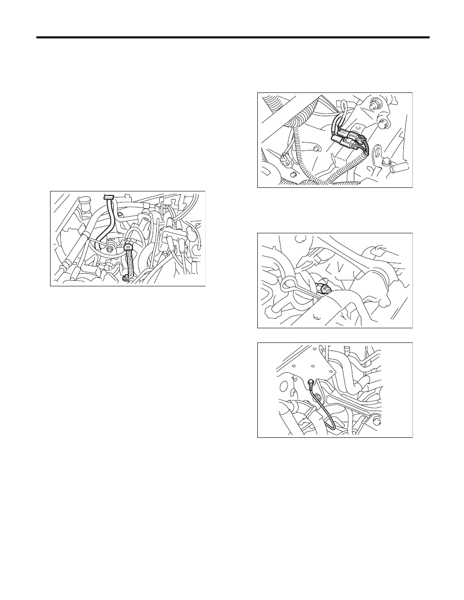
8) Disconnect the connector back-up light switch &
neutral position switch.
• Non-turbo model

• Turbo model

9) Disconnect the ground cable.

10) Remove the starter. <Ref. to SC(H4SO)-6, RE-
MOVAL, Starter.>

MT-00062

(A) Neutral position switch connector (Brown)

(B) Back-up light switch connector (Gray)

MT-00104

(A)

(B)

MT-00105

MT-01814

5MT-25

Manual Transmission Assembly

MANUAL TRANSMISSION AND DIFFERENTIAL

11) Remove the operating cylinder from the trans-
mission, and suspend on a wire.

12) Remove the pitching stopper.

13) Set the ST.
ST

41099AC000 ENGINE SUPPORT ASSY

14) Lift up the vehicle.
15) Remove the front and center exhaust pipes.
(Non-turbo model) <Ref. to EX(H4SO)-7, REMOV-
AL, Center Exhaust Pipe.>
16) Remove the center exhaust pipe. (Turbo mod-
el) <Ref. to EX(H4DOTC)-7, REMOVAL, Center
Exhaust Pipe.>

17) Remove the rear exhaust pipe and muffler. 
• Non-turbo model
<Ref. to EX(H4SO)-8, REMOVAL, Rear Exhaust
Pipe.> <Ref. to EX(H4SO)-10, REMOVAL, Muf-
fler.>
• Turbo model
<Ref. to EX(H4DOTC)-12, REMOVAL, Rear Ex-
haust Pipe.> <Ref. to EX(H4DOTC)-14, REMOV-
AL, Muffler.>

CAUTION:
When removing the exhaust pipes, be careful
each exhaust pipe does not drop out.
18) Remove the bolts which hold upper side of
transmission to engine.

19) Remove the heat shield cover.

20) Remove the hanger bracket from the right side
of transmission.

21) Remove the propeller shaft. <Ref. to DS-10,
REMOVAL, Propeller Shaft.>

MT-01220

MT-01556

MT-01226

ST

MT-01524

MT-01660

MT-00074

5MT-26

Manual Transmission Assembly

MANUAL TRANSMISSION AND DIFFERENTIAL

22) Remove the gear shift rod and the stay from the
transmission.

(1) Disconnect the stay from the transmission.
(2) Remove the gear shift rod from the trans-
mission.

23) Remove the stabilizer link from the front arm.

24) Remove the bolt securing the ball joint of the
front arm to the housing, then separate the front
arms and the housing.

25) Using a crowbar, remove the left and right front
drive shaft from the transmission.

26) Remove the bolts and nuts which hold lower
side of transmission to engine.

27) Place the transmission jack under the transmis-
sion.

CAUTION:
Always support the transmission case with a
transmission jack.

(A) Stay

(B) Gear shift rod

(A) Front arm

(B) Ball joint

(C) Stabilizer link

MT-00075

(A)

(B)

(B)

MT-00988

MT-00987

(A)

(C)

(B)

(A) Bar

MT-01017

(A)

MT-00077

MT-00078

5MT-27

Manual Transmission Assembly

MANUAL TRANSMISSION AND DIFFERENTIAL

28) Remove the front crossmember and rear cross-
member from the vehicle.

29) Tighten the turnbuckle of the ST while lowering
the transmission jack, to tilt the engine assembly
towards the back.
30) Remove the transmission.

NOTE:
Move the transmission jack towards the rear until
the main shaft is withdrawn from the clutch disc.
31) Separate the transmission assembly from the
transmission cushion rubber.

B: INSTALLATION

1) Replace the differential side retainer oil seal.
<Ref. to 5MT-34, REPLACEMENT, Differential
Side Retainer Oil Seal.>
ST

18675AA000

DIFFERENTIAL SIDE OIL 
SEAL INSTALLER

NOTE:
Be sure to replace the differential side retainer oil
seal after the removing the front drive shaft.

2) Install the transmission cushion rubber to the
transmission assembly, and tighten bolt (A).
3) Install the transmission cushion rubber to the
center crossmember, and tighten the nut (B).

Tightening torque:

Bolt (A)

35 N·m (3.6 kgf-m, 25.8 ft-lb)

Nut (B)

35 N·m (3.6 kgf-m, 25.8 ft-lb)

4) Install the transmission onto the engine.

(1) Lift up the transmission gradually using a
transmission jack.
(2) Engage at the spline section.

NOTE:
Be careful not to hit the main shaft against the
clutch housing cover.
5) While raising the transmission jack, loosen the
turnbuckle of the ST, and set the engine unit to the
original position.

MT-01671

ST

MT-00103

MT-01676

(A)

(A)

(B)


Content   ..  780  781  782  783   ..