Subaru Legacy IV (2008 year). Manual - part 765


  Index      Subaru     Subaru Legacy IV - service repair manual 2008 year


Search            


Content   ..  763  764  765  766   ..


Subaru Legacy IV (2008 year). Manual - part 765


5AT(diag)-75

Diagnostic Procedure with Diagnostic Trouble Code (DTC)

AUTOMATIC TRANSMISSION (DIAGNOSTICS)

X: DTC P0768 SHIFT SOLENOID “D” ELECTRICAL

DTC DETECTING CONDITION:
The output signal circuit of direct clutch linear solenoid is open or shorted.
TROUBLE SYMPTOM:
Locked to 1st or 4th gear.
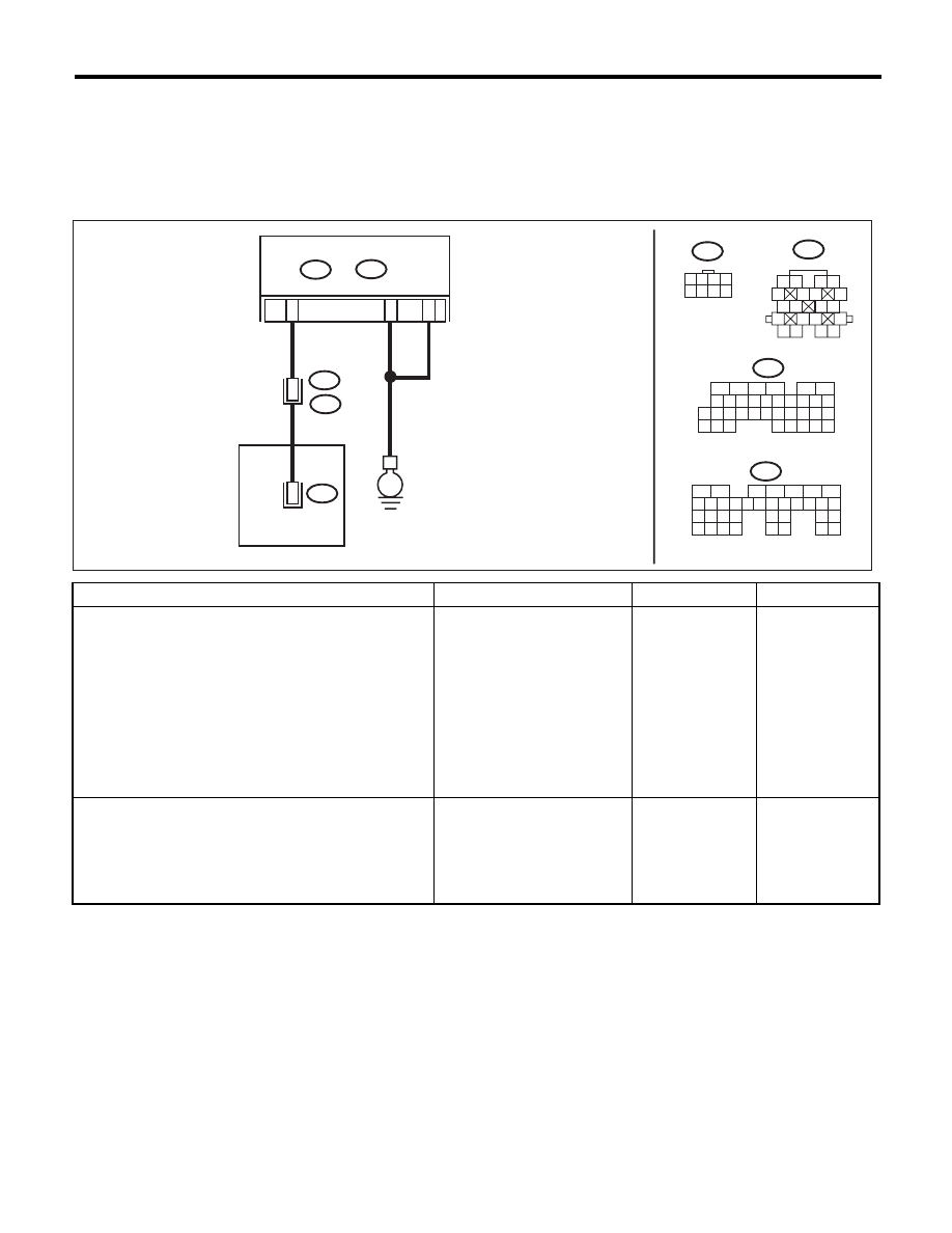
WIRING DIAGRAM:

Step

Check

Yes

No

1

CHECK HARNESS CONNECTOR BETWEEN 
TCM AND TRANSMISSION.
1) Turn the ignition switch to OFF.
2) Disconnect the connectors from TCM and 
transmission.
3) Measure the resistance of harness between 
TCM and transmission connector.

Connector & terminal

(B55) No. 22 — Chassis ground:
(B55) No. 23 — Chassis ground:
(B54) No. 1 — (B11) No. 16:

Is the resistance less than 1 

:? Go to step 2.

Repair the open 
circuit of harness 
between TCM con-
nector and trans-
mission connector.

2

CHECK HARNESS CONNECTOR BETWEEN 
TCM AND CHASSIS GROUND.
Measure the resistance of harness between 
TCM connector and chassis ground.

Connector & terminal

(B54) No. 1 — Chassis ground:

Is the resistance 1 M

: or 

more?

Go to step 3.

Repair the short 
circuit of harness 
between TCM con-
nector and trans-
mission connector.

AT-04361

A1

B11

T11

T4

16

4

CONTROL VALVE  BODY

DIRECT CLUTCH

LINEAR SOLENOID

B11

1

2

3 4

5

6 7

8

9

13

14 15

20

19

17

16

10

11 12

18

5

6

7 8

2

1

9

4

3

10

24

22 23

25

11 12 13 14 15

26 27

28

16

17 18 19 20 21

33 34

29

32

30

31

35

1 2 3 4
5 6 7 8

T11

5

6

7

2

1

3

4

29

10 11 12 13 14 15

25

24

16

30

9

8

17 18 19

20
28

21 22 23

32

31

26 27

33

34 35

TCM

B54

A:

B55

B:

B22

B23

E

B54

A:

B55

B:

5AT(diag)-76

Diagnostic Procedure with Diagnostic Trouble Code (DTC)

AUTOMATIC TRANSMISSION (DIAGNOSTICS)

3

CHECK HARNESS CONNECTOR BETWEEN 
TRANSMISSION AND CONTROL VALVE 
BODY.
1) Turn the ignition switch to OFF.
2) Disconnect the connector from transmis-
sion.
3) Remove the transmission connector from 
bracket.
4) Lift up the vehicle.

NOTE:
Raise all wheels off the floor.
5) Drain the ATF.

CAUTION:
Do not drain ATF until it cools down.
6) Remove the oil pan, and disconnect the 
control valve body connector.
7) Measure the resistance between transmis-
sion connector and control valve body connec-
tor.

Connector & terminal

(T4) No. 16 — (T11) No. 4:

Is the resistance less than 1 

:? Go to step 4.

Repair the open 
circuit of harness 
between transmis-
sion connector and 
control valve body 
connector.

4

CHECK HARNESS CONNECTOR BETWEEN 
TRANSMISSION AND CONTROL VALVE 
BODY.
Measure the resistance between transmission 
ground and control valve body connector.

Connector & terminal

(T11) No. 4 — Transmission ground:

Is the resistance 1 M

: or 

more?

Repair the open 
circuit of harness 
between control 
valve body con-
nector and trans-
mission ground.

Go to step 5.

5

CHECK DIRECT CLUTCH LINEAR SOLE-
NOID.
Measure the resistance of harness connector 
between control valve body connector and 
transmission ground.

Connector & terminal

(T11) No. 4 — Transmission ground:

Is the resistance 3 — 9 

:?

Go to step 6.

Replace the con-
trol valve body. 
<Ref. to 5AT-57, 
Control Valve 
Body.>

6

CHECK POOR CONTACT.
Check that there are no poor contact in TCM 
connector, transmission connector and control 
valve body connector.

Is there any loosing terminal, 
entering foreign matter, damag-
ing connector body?

Repair the poor 
contact.

Go to step 7.

7

CHECK AFTER REPAIR.
1) Perform the Clear Memory Mode.
2) Drive for a while, read the DTC, and check 
that there is no faulty.

Is DTC displayed?

Replace the TCM. 
<Ref. to 5AT-60, 
Transmission Con-
trol Module 
(TCM).>

Temporary poor 
contact or open cir-
cuit occurs. 
Recheck that the 
harness connector 
has no faulty.

Step

Check

Yes

No

5AT(diag)-77

Diagnostic Procedure with Diagnostic Trouble Code (DTC)

AUTOMATIC TRANSMISSION (DIAGNOSTICS)

Y: DTC P0771 SHIFT SOLENOID “E” PERFORMANCE OR STUCK OFF

DTC DETECTING CONDITION:
Output signal of forward brake linear solenoid does not match the oil pressure.
TROUBLE SYMPTOM:
Locked to 2nd, 3rd, 4th gear.
WIRING DIAGRAM:

Step

Check

Yes

No

1

CHECK HARNESS CONNECTOR BETWEEN 
TCM AND TRANSMISSION.
1) Turn the ignition switch to OFF.
2) Disconnect the connectors from TCM and 
transmission.
3) Measure the resistance of harness between 
TCM and transmission connector.

Connector & terminal

(B55) No. 22 — Chassis ground:
(B55) No. 23 — Chassis ground:
(B54) No. 19 — (B11) No. 13:
(B54) No. 21 — (B11) No. 9:

Is the resistance less than 1 

:? Go to step 2.

Repair the open 
circuit of harness 
between TCM and 
transmission con-
nector.

2

CHECK HARNESS CONNECTOR BETWEEN 
TCM AND CHASSIS GROUND.
Measure the resistance between TCM connec-
tor and chassis ground.

Connector & terminal

(B54) No. 21 — Chassis ground:

Is the resistance 1 M

: or 

more?

Go to step 3.

Repair the short 
circuit of harness 
between TCM and 
transmission con-
nector.

3

CHECK INPUT SIGNAL FOR TCM USING 
SUBARU SELECT MONITOR.
1) Connect all connectors.
2) Turn the ignition switch to ON. (engine OFF)
3) Check input signal of “Fwd/B hydraulic pres-
sure SW”.

Is OFF displayed?

Go to step 4.

Go to step 6.

AT-04362

A21

 A1

9

CONTROL VALVE  BODY

B11

T4

7

T10

T11

9

13

10

FORWARD 

BRAKE

OIL PRESSURE 

SWITCH

FORWARD 
BRAKE
LINEAR
SOLENOID

B11

1 2

5

6 7

8

13

14 15

16

9 10

11 12

3 4

17 18

19 20

T11

1 2 3 4
5 6 7 8

16

10 11 12 13 14 15

25

24

30

9

8

7

17 18 19 20
28

21 22 23

29

32

31

1

2

3

4

5

6

27

26

33 34 35

T10

1 2 3 4
6 7 8 9

5

10

5

6

7

2

1

3

4

29

10 11 12 13 14 15

25

24

16

30

9

8

17 18 19

20
28

21 22 23

32

31

26 27

33

34 35

TCM

B54

A:

B55

B:

B22

B23

E

B54

A:

B55

B:

5AT(diag)-78

Diagnostic Procedure with Diagnostic Trouble Code (DTC)

AUTOMATIC TRANSMISSION (DIAGNOSTICS)

4

CHECK INPUT SIGNAL FOR TCM USING 
SUBARU SELECT MONITOR.
1) Turn the ignition switch to OFF.
2) Turn the ignition switch to ON. (Engine ON)
3) Drive the vehicle on 2nd speed of manual 
mode 15 km/h (9 MPH) with checking current 
gear position using Subaru Select Monitor.
4) Check input signal of “Fwd/B hydraulic pres-
sure SW”.

Is ON displayed?

Even if the AT OIL 
TEMP light blinks, 
the system is in 
normal condition. 
A temporary poor 
contact of connec-
tor or harness may 
be the cause. 
Repair the poor 
contact of harness 
in the solenoid out-
put and oil pres-
sure SW input.

Go to step 5.

5

CHECK HARNESS CONNECTOR BETWEEN 
TRANSMISSION AND CONTROL VALVE 
BODY.
1) Turn the ignition switch to OFF.
2) Disconnect the connector from transmis-
sion.
3) Remove the transmission connector from 
bracket.
4) Lift up the vehicle.

NOTE:
Raise all wheels off the floor.
5) Drain the ATF.

CAUTION:
Do not drain ATF until it cools down.
6) Remove the oil pan, and disconnect the 
control valve body connector.
7) Measure the resistance between transmis-
sion connector and control valve body connec-
tor.

Connector & terminal

(T4) No. 13 — (T11) No. 7:
(T4) No. 9 — (T10) No. 10:

Is the resistance less than 1 

:? Replace the con-

trol valve body. 
<Ref. to 5AT-57, 
Control Valve 
Body.>

Replace the trans-
mission harness 
assembly.

6

CHECK HARNESS CONNECTOR BETWEEN 
TRANSMISSION AND CONTROL VALVE 
BODY.
1) Turn the ignition switch to OFF.
2) Disconnect the connector from transmis-
sion.
3) Remove the transmission connector from 
bracket.
4) Lift up the vehicle.

NOTE:
Raise all wheels off the floor.
5) Drain the ATF.

CAUTION:
Do not drain ATF until it cools down.
6) Remove the oil pan, and disconnect the 
control valve body connector.
7) Check the insulation of transmission har-
ness assembly.

Connector & terminal

(T10) No. 10 — Transmission ground:

Is the resistance 1 M

: or 

more?

Replace the con-
trol valve body. 
<Ref. to 5AT-57, 
Control Valve 
Body.>

Repair the short 
circuit of harness 
between transmis-
sion connector and 
control valve body 
connector.

Step

Check

Yes

No


Content   ..  763  764  765  766   ..