Subaru Legacy IV (2008 year). Manual - part 733


  Index      Subaru     Subaru Legacy IV - service repair manual 2008 year


Search            


Content   ..  731  732  733  734   ..


Subaru Legacy IV (2008 year). Manual - part 733


5AT-56

Turbine Speed Sensor 1

AUTOMATIC TRANSMISSION

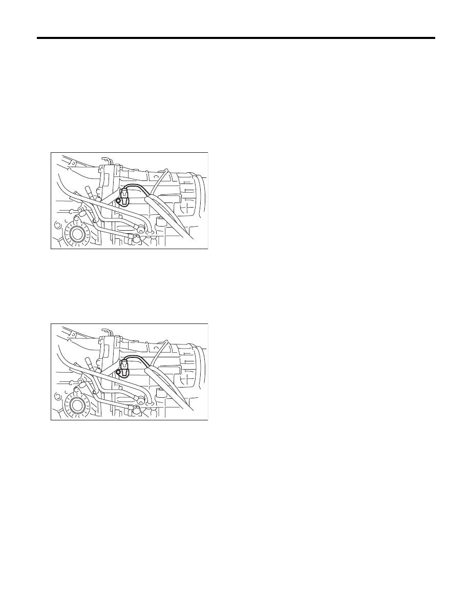
16.Turbine Speed Sensor 1

A: REMOVAL

1) Remove the intercooler. (Turbo model) <Ref. to
IN(H4DOTC)-12, REMOVAL, Intercooler.>
2) Remove the air intake chamber. (Non-turbo
model) <Ref. to IN(H6DO)-7, REMOVAL, Air Intake
Chamber.>
3) Lift up the vehicle.
4) Disconnect the turbine speed sensor 1 connec-
tor.

5) Remove the turbine speed sensor 1.

B: INSTALLATION

1) Install the turbine speed sensor 1.

Tightening torque:

7 N·m (0.7 kgf-m, 5.2 ft-lb)

2) Connect the turbine speed sensor 1 connector.

3) Lower the vehicle.
4) Install the intercooler. (Turbo model) <Ref. to
IN(H4DOTC)-13, INSTALLATION, Intercooler.>
5) Install the air intake chamber. (Non-turbo model)
<Ref. to IN(H6DO)-7, INSTALLATION, Air Intake
Chamber.>

AT-01387

AT-01387

5AT-57

Control Valve Body

AUTOMATIC TRANSMISSION

17.Control Valve Body

A: REMOVAL

1) Set the vehicle on a lift.
2) Disconnect the ground cable from battery.
3) Lift up the vehicle.
4) Clean the transmission exterior.
5) Remove the ATF drain plug to drain ATF.

CAUTION:
Immediately after the vehicle has been running
or after idling for a long time, the ATF will be
hot. Be careful not to burn yourself.
6) Tighten the ATF drain plug.

NOTE:
Use a new gasket.

Tightening torque:

20 N·m (2.0 kgf-m, 14.8 ft-lb)

7) Remove the oil pan.

CAUTION:
Be sure to prevent the entering of dust and oth-
er foreign matters into oil pan.
8) Remove the magnet.

9) Clean the magnet.
10) Completely remove the remaining liquid gasket
on the transmission case and oil pan.
11) Disconnect the control valve connector and
front vehicle speed sensor connector.

12) Remove the control valve body.

NOTE:
The control valve body is replaced as an assembly
only, because it is a non-disassembly part.

(A) Control valve connector

(B) Front vehicle speed sensor connector

AT-01959

AT-04220

(A)

(B)

(A)

AT-04221

5AT-58

Control Valve Body

AUTOMATIC TRANSMISSION

B: INSTALLATION

1) Check the control valve body for dust and other
foreign matter.
2) Install the control valve body to transmission by
equally tightening the bolts.

Tightening torque:

8 N·m (0.8 kgf-m, 5.9 ft-lb)

3) Connect the control valve connector.

4) Attach the magnet at the specified position of the
oil pan.

5) Apply liquid gasket to the oil pan.

Liquid gasket:

THREE BOND 1217B (Part No. K0877YA020) 
or equivalent

6) Install the oil pan by equally tightening the bolts.

Tightening torque:

5 N·m (0.5 kgf-m, 3.7 ft-lb)

7) Pour ATF through the oil charge pipe. <Ref. to
5AT-28, Automatic Transmission Fluid.>
8) Check the ATF level. <Ref. to 5AT-28, INSPEC-
TION, Automatic Transmission Fluid.>
9) Perform Clear Memory 2 operation. <Ref. to
5AT(diag)-20, CLEAR MEMORY MODE, OPERA-
TION, Subaru Select Monitor.>
10) Execute the learning control promotion. <Ref.
to 5AT(diag)-24, PROCEDURE, Learning Con-
trol.>
11) Perform the inspection at the end of repair
work, and make sure there is no faulty as below;
• Excessive shift shock
• Oil leakage from the transmission body, etc.
• Occurrence of noise caused by interference etc.

C: INSPECTION

Check each parts for holes, damages or other for-
eign matters.

(1) 30 mm (1.18 in)

(2) 40 mm (1.57 in)

(A) Control valve connector

(B) Front vehicle speed sensor connector

AT-04222

(1)

(1)

(1)

(1)

(1)

(1)

(2)

(1)

(1)

(2)

(1)

(1)

(1)

AT-04220

(A)

(B)

(A)

AT-01959

AT-01955

5AT-59

ATF Filter

AUTOMATIC TRANSMISSION

18.ATF Filter

A: REMOVAL

NOTE:
The ATF filter is maintenance free.
1) Disconnect the battery ground cable and remove
the battery from the vehicle.

2) Remove the harness securing bracket.

3) Using the ST, remove the ATF filter.
ST

498545400

OIL FILTER WRENCH

B: INSTALLATION

1) Apply a thin coat of ATF to the oil seal part of
new ATF filter.
2) Install the ATF filter. Turn it by hand, being care-
ful not to damage oil seal.
3) Tighten the ATF filter using ST.
Calculate the ATF filter tightening torque using fol-
lowing formula.
T2 = L2/(L1 + L2) × T1
T1: 14 N·m (1.4 kgf-m, 10.3 ft-lb)
[Required torque setting]
T2: Tightening torque
L1: ST length 78 mm (3.07 in)
L2: Torque wrench length
Example:

NOTE:
Align the ST with the torque wrench while tighten-
ing the ATF filter.
ST

498545400

OIL FILTER WRENCH

4) Fill ATF. <Ref. to 5AT-28, Automatic Transmis-
sion Fluid.>
5) Inspect the level of ATF. <Ref. to 5AT-28, IN-
SPECTION, Automatic Transmission Fluid.>
6) Install the harness securing bracket.
7) Install the battery.

C: INSPECTION

Check for rust, hole, ATF leaks or other damage.
Replace the part if any damage is found in the in-
spection.

IN-00203

AT-01381

Torque wrench length

mm (in)

Tightening torque

N·m (kgf-m, ft-lb)

100 (3.94)

7.7 (0.8, 5.7)

150 (5.91)

9.0 (0.9, 6.6)

200 (7.87)

10 (1.0, 7.4)


Content   ..  731  732  733  734   ..