Subaru Legacy IV (2008 year). Manual - part 730


  Index      Subaru     Subaru Legacy IV - service repair manual 2008 year


Search            


Content   ..  728  729  730  731   ..


Subaru Legacy IV (2008 year). Manual - part 730


5AT-44

Automatic Transmission Assembly

AUTOMATIC TRANSMISSION

11) Install the torque converter to drive plate.

CAUTION:
• Be careful not to drop bolts into converter
housing.
• Be careful not to damage the mounting bolts.

(1) Install the bolts which hold torque converter
to drive plate.
(2) Install all four bolts by rotating the crank pul-
ley a little at a time.
(3) Install the service hole.

Tightening torque:

25 N·m (2.5 kgf-m, 18.4 ft-lb)

12) Remove the ST and install the pitching stopper
bracket.

Tightening torque:

41 N·m (4.2 kgf-m, 30.2 ft-lb)

13) Install the pitching stopper.

Tightening torque:

T1: 50 N·m (5.1 kgf-m, 36.9 ft-lb)
T2: 58 N·m (5.9 kgf-m, 42.8 ft-lb)

14) Lift up the vehicle.

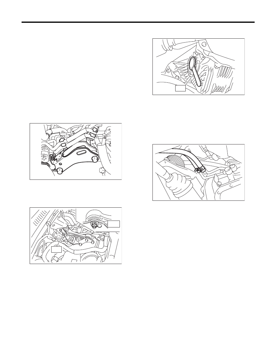
15) Set the ST to side retainer.
ST

28399SA010

OIL SEAL PROTECTOR

16) Install the front drive shaft into the transmis-
sion.

NOTE:
Replace the circlip of drive shaft with a new part.
17) Install the front drive shaft into transmission, re-
move the ST and insert the drive shaft securely.
18) Install the inlet and outlet hoses to the ATF inlet
and outlet pipes.

19) Insert the ball joint into housing. <Ref. to FS-16,
INSTALLATION, Front Ball Joint.>
20) Install the front stabilizer bracket. <Ref. to FS-
15, INSTALLATION, Front Stabilizer.>

AT-04234

T2

T1

AT-03874

AT-00110

ST

AT-01390

5AT-45

Automatic Transmission Assembly

AUTOMATIC TRANSMISSION

21) Install the clutch housing cover securing bolts.

22) Install the front crossmember support plate.
<Ref. to FS-14, INSTALLATION, Front Crossmem-
ber Support Plate.>
23) Install the propeller shaft. <Ref. to DS-11, IN-
STALLATION, Propeller Shaft.>
24) Install the shift select cable. <Ref. to CS-30, IN-
STALLATION, Select Cable.>
25) Install the turbine speed sensor 1 and harness,
and then connect the connector.

Tightening torque:

7 N·m (0.7 kgf-m, 5.2 ft-lb)

26) Install the oil charge pipe.

NOTE:
Use new bolts.

Tightening torque:

38 N·m (3.9 kgf-m, 28.0 ft-lb)

27) Install the heat shield cover.

28) Install the center, rear exhaust pipes and the
muffler. (Turbo model) <Ref. to EX(H4DOTC)-9,
INSTALLATION, Center Exhaust Pipe.> <Ref. to
EX(H4DOTC)-13, INSTALLATION, Rear Exhaust
Pipe.> <Ref. to EX(H4DOTC)-14, INSTALLATION,
Muffler.>
29) Install the front exhaust pipe, rear exhaust pipe
and muffler. (Non-turbo model) <Ref. to
EX(H6DO)-5, INSTALLATION, Front Exhaust
Pipe.> <Ref. to EX(H6DO)-8, INSTALLATION,
Rear Exhaust Pipe.> <Ref. to EX(H6DO)-9, IN-
STALLATION, Muffler.>
30) Install the under cover.
31) Lower the vehicle.
32) Install the air cleaner case. (Turbo model)
<Ref. to IN(H4DOTC)-8, INSTALLATION, Air
Cleaner Case.>
33) Install the air intake duct. (Turbo model) <Ref.
to IN(H4DOTC)-9, INSTALLATION, Air Intake
Duct.>

AT-01373

AT-01374

AT-01736

AT-01371

AT-01331

5AT-46

Automatic Transmission Assembly

AUTOMATIC TRANSMISSION

34) Connect the following connectors.
• Turbo model

• Non-turbo model

35) Install the engine hanger. (Turbo model)

36) Install the engine hanger rear, and then con-
nect the engine harness connector. (Non-turbo
model)

37) Install the water by-pass pipe. (Turbo model)

38) Pour ATF from the oil charge pipe. <Ref. to
5AT-28, Automatic Transmission Fluid.>
39) Install the air breather hose. <Ref. to 5AT-65,
INSTALLATION, Air Breather Hose.>
40) Install the intercooler. (Turbo model) <Ref. to
IN(H4DOTC)-13, INSTALLATION, Intercooler.>
41) Install the air intake chamber and intake boot.
(Non-turbo model) <Ref. to IN(H6DO)-7, INSTAL-
LATION, Air Intake Chamber.>
42) Install the collector cover.
43) Connect the ground cable to battery.
44) Perform Clear Memory 2 operation. <Ref. to
5AT(diag)-20, CLEAR MEMORY MODE, OPERA-
TION, Subaru Select Monitor.>
45) Execute the learning control promotion. <Ref.
to 5AT(diag)-24, PROCEDURE, Learning Con-
trol.>
46) Perform the inspection at the end of repair
work, and make sure there is no faulty as below;
• Excessive shift shock
• Oil leakage from the transmission body, etc.
• Occurrence of noise caused by interference etc.

(1) Rear oxygen sensor connector

(2) Transmission harness connectors

(1) Front oxygen (A/F) and rear oxygen sensor 

connector

(2) Transmission harness connectors

AT-04406

(1)

(2)

(2)

(2)

AT-04383

(2)

(2)

(2)

(1)

(1)

(1)

AT-04407

(A) Engine harness connectors

(B) Engine hanger rear

(B)

(A)

(A)

AT-02023

AT-01366

5AT-47

Transmission Mounting System

AUTOMATIC TRANSMISSION

10.Transmission Mounting 

System

A: REMOVAL

1. PITCHING STOPPER

1) Disconnect the ground cable from battery.
2) Remove the intercooler. (Turbo model)
<Ref. to IN(H4DOTC)-12, REMOVAL, Intercool-
er.>
3) Remove the air intake chamber. (Non-turbo
model) <Ref. to IN(H6DO)-7, REMOVAL, Air Intake
Chamber.>
4) Remove the pitching stopper.

2. TRANSMISSION REAR CROSSMEMBER & 
REAR CUSHION RUBBER

1) Disconnect the ground cable from battery.
2) Lift up the vehicle.
3) Remove the center and rear exhaust pipes and
the muffler. (Turbo model)
<Ref. to EX(H4DOTC)-7, REMOVAL, Center Ex-
haust Pipe.> <Ref. to EX(H4DOTC)-12, REMOV-
AL, Rear Exhaust Pipe.> <Ref. to EX(H4DOTC)-
14, REMOVAL, Muffler.>
4) Remove the front exhaust pipe, rear exhaust
pipe and muffler. (Non-turbo model) <Ref. to
EX(H6DO)-4, REMOVAL, Front Exhaust Pipe.>
<Ref. to EX(H6DO)-7, REMOVAL, Rear Exhaust
Pipe.> <Ref. to EX(H6DO)-9, REMOVAL, Muffler.>
5) Remove the heat shield cover.

6) Set the transmission jack under transmission.
Make sure that the support plate of transmission
jack does not touch the oil pan.

7) Remove the transmission rear crossmember.

8) Remove the rear cushion rubber from transmis-
sion.

AT-03873

AT-01331

AT-01377


Content   ..  728  729  730  731   ..