Subaru Legacy IV (2008 year). Manual - part 729


  Index      Subaru     Subaru Legacy IV - service repair manual 2008 year


Search            


Content   ..  727  728  729  730   ..


Subaru Legacy IV (2008 year). Manual - part 729


5AT-40

Automatic Transmission Assembly

AUTOMATIC TRANSMISSION

13) Separate the torque converter from drive plate.

CAUTION:
• Be careful not to drop bolts into converter
housing.
• Be careful not to damage the mounting bolts.

(1) Remove the service hole plug.
(2) Remove the bolts which hold torque con-
verter to drive plate.
(3) Remove the four bolts by rotating the crank
pulley a little at a time.
(4) Make sure the torque converter moves free-
ly by rotating with finger through the starter in-
stallation hole.

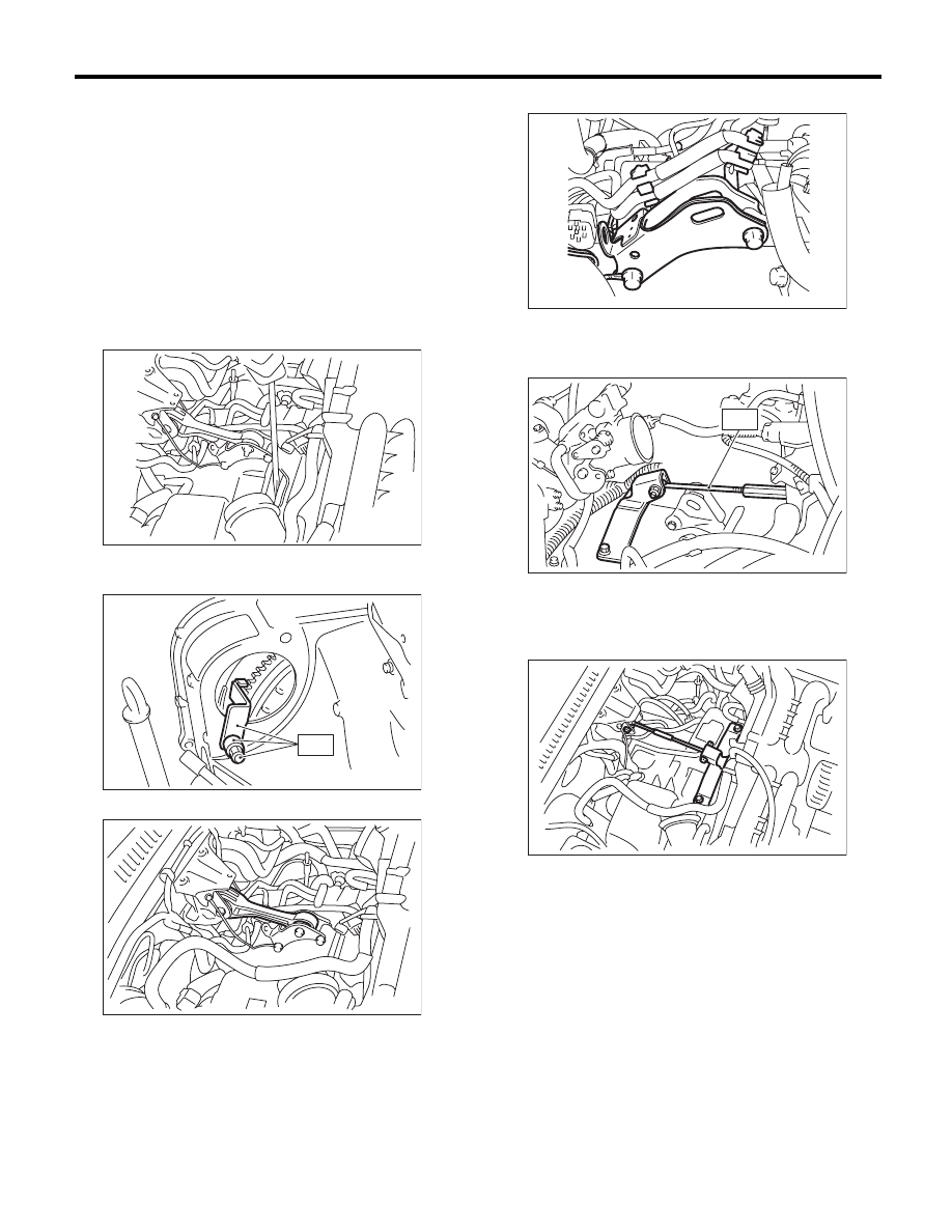
14) Attach the ST to the converter case.
ST

498277200

STOPPER SET

15) Remove the pitching stopper.

16) Remove the pitching stopper bracket.

17) Set the ST.
• Turbo model
ST

41099AC000 ENGINE SUPPORT ASSY

• Non-turbo model
ST1

41099AA010

ENGINE SUPPORT 
BRACKET

ST2

41099AA020

ENGINE SUPPORT

18) Remove the air intake duct. (Turbo model)
<Ref. to IN(H4DOTC)-9, REMOVAL, Air Intake
Duct.>
19) Remove the air cleaner case. (Turbo model)
<Ref. to IN(H4DOTC)-8, REMOVAL, Air Cleaner
Case.>
20) Lift up the vehicle. (Turbo model)
21) Remove the under cover. (Turbo model)
22) Remove the center and rear exhaust pipes and
the muffler. (Turbo model) <Ref. to EX(H4DOTC)-
7, REMOVAL, Center Exhaust Pipe.> <Ref. to
EX(H4DOTC)-12, REMOVAL, Rear Exhaust
Pipe.> <Ref. to EX(H4DOTC)-14, REMOVAL, Muf-
fler.>

AT-01367

AT-00103

ST

AT-03873

AT-04234

AT-02984

ST

AT-01370

5AT-41

Automatic Transmission Assembly

AUTOMATIC TRANSMISSION

23) Remove the front exhaust pipe, rear exhaust
pipe and muffler. (Non-turbo model) <Ref. to
EX(H6DO)-4, REMOVAL, Front Exhaust Pipe.>
<Ref. to EX(H6DO)-7, REMOVAL, Rear Exhaust
Pipe.> <Ref. to EX(H6DO)-9, REMOVAL, Muffler.>
24) Remove the transmission mounting bolt (upper
side).

25) Remove the heat shield cover.

26) Remove the ATF drain plug to drain ATF.

27) Remove the oil charge pipe.

28) Disconnect the connector from turbine speed
sensor 1.

29) Remove the turbine speed sensor 1 connector
mounting bolt and rotate the sensor by 180°.

CAUTION:
Failure to follow this procedure may cause the
interference between vehicle body and sensor
while removing/installing transmission, and re-
sulting in damage.

30) Remove the propeller shaft. <Ref. to DS-10,
REMOVAL, Propeller Shaft.>
31) Remove the shift select cable. <Ref. to CS-28,
REMOVAL, Select Cable.>
32) Disconnect the hose from the ATF inlet and
outlet pipes.

33) Remove the front crossmember support plate.
<Ref. to FS-14, REMOVAL, Front Crossmember
Support Plate.>

(A) Oil pan

(B) ATF drain plug

AT-03237

AT-01331

(A)

AT-03126

(B)

AT-01371

AT-01642

AT-01640

AT-01390

5AT-42

Automatic Transmission Assembly

AUTOMATIC TRANSMISSION

34) Remove the two clutch housing cover securing
bolts.

35) Remove the front stabilizer bracket. <Ref. to
FS-15, REMOVAL, Front Stabilizer.>
36) Remove the bolts which secure front ball joint
to the housing. <Ref. to FS-16, REMOVAL, Front
Ball Joint.>
37) Pull out the drive shaft from transmission.
38) Set the transmission jack under the transmis-
sion.

39) Remove the rear crossmember.

40) Remove the transmission mounting bolt and
nut (lower side).

41) Remove the transmission.

NOTE:
• Turn the engine support assembly from the vehi-
cle under body to the left (to shorten the engine
support length), and lower the rear of the engine for
easy disassembly.
• Be careful not to allow breather pipe and etc. to
touch the vehicle body when detaching the auto-
matic transmission assembly by pulling it back-
ward.

AT-01373

AT-01374

AT-01376

AT-01377

AT-03238

5AT-43

Automatic Transmission Assembly

AUTOMATIC TRANSMISSION

B: INSTALLATION

1) Replace the front differential side retainer oil
seal.

(1) Remove the oil seal by using flat tip screw-
driver etc.
(2) Install a new oil seal using ST.

ST

18675AA000

DIFFERENTIAL SIDE OIL 
SEAL INSTALLER

NOTE:
• Apply oil to the oil seal lips.
• Be sure to replace the differential side oil seal af-
ter the procedure of removing front drive shaft from
transmission.

2) Attach the ST to converter case.
ST

498277200

STOPPER SET

3) Install the transmission onto the engine.

(1) Lift up the transmission gradually using
transmission jack.
(2) Engage at the spline.

4) Install the engine mounting bolt and nut (lower
side).

Tightening torque:

50 N·m (5.1 kgf-m, 36.9 ft-lb)

5) Install the transmission rear crossmember.

Tightening torque:

75 N·m (7.6 kgf-m, 55.3 ft-lb)

6) Remove the transmission jack.
7) Lower the vehicle.
8) Install the engine mounting bolt (upper side).

Tightening torque:

50 N·m (5.1 kgf-m, 36.9 ft-lb)

9) Remove the ST from converter case.
10) Install the starter. <Ref. to SC(H4SO)-6, IN-
STALLATION, Starter.>

AT-00029

ST

AT-00103

ST

AT-03238

AT-01377

AT-03237


Content   ..  727  728  729  730   ..