Subaru Legacy IV (2008 year). Manual - part 711
4AT(diag)-65
Diagnostic Procedure with Diagnostic Trouble Code (DTC)
AUTOMATIC TRANSMISSION (DIAGNOSTICS)
R: DTC P0758 SHIFT SOLENOID “B” ELECTRICAL
DTC DETECTING CONDITION:
Output signal circuit of 2-4 brake duty solenoid is open or shorted.
TROUBLE SYMPTOM:
Excessive shift shock
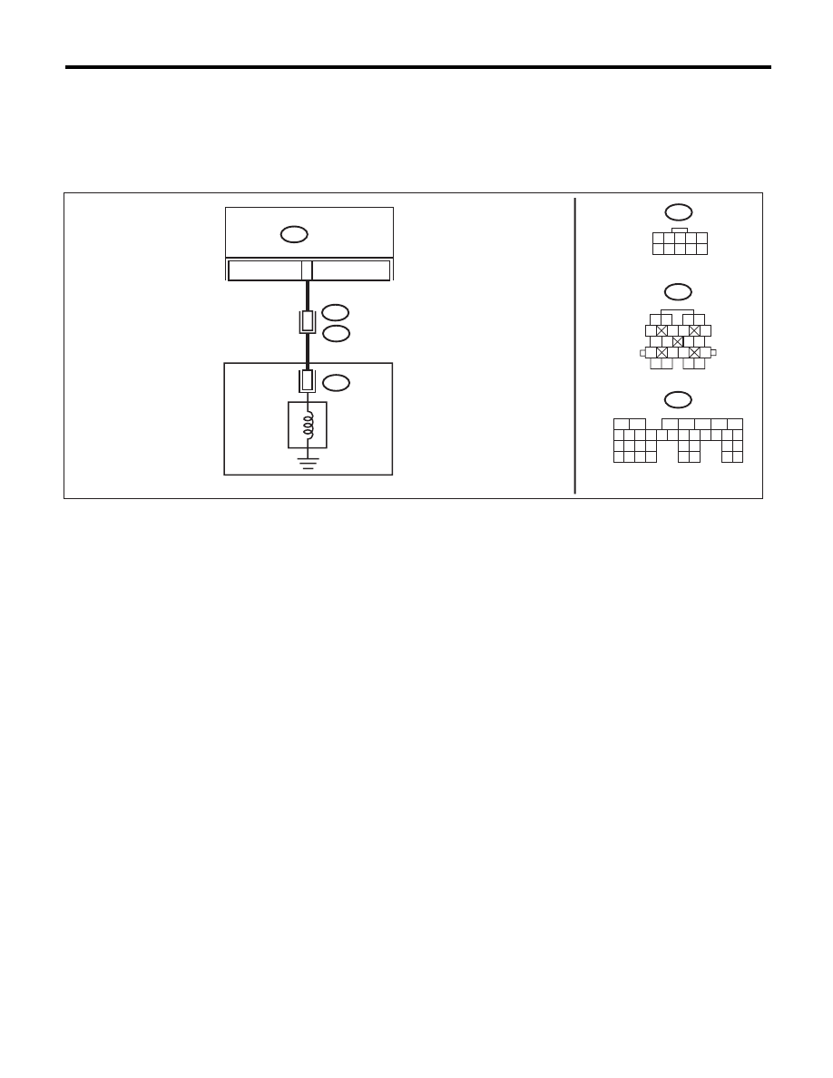
WIRING DIAGRAM:
AT-04771
TCM
B11
1
2
3 4
5
6 7
8
9
13
14 15
20
19
17
16
10
11 12
18
4
B55
B11
AT 2
T4
3
8
B55
5
6
7
2
1
3
4
29
10 11 12 13 14 15
25
24
16
30
9
8
17 18 19
20
28
21 22 23
32
31
26 27
33
34 35
AT2
10
9
8
7
6
5
4
3
2
1
CONTROL VALVE BODY
2-4 BRAKE
DUTY
SOLENOID