Subaru Legacy IV (2008 year). Manual - part 579
EN(H6DO)(diag)-289
Diagnostic Procedure with Diagnostic Trouble Code (DTC)
ENGINE (DIAGNOSTICS)
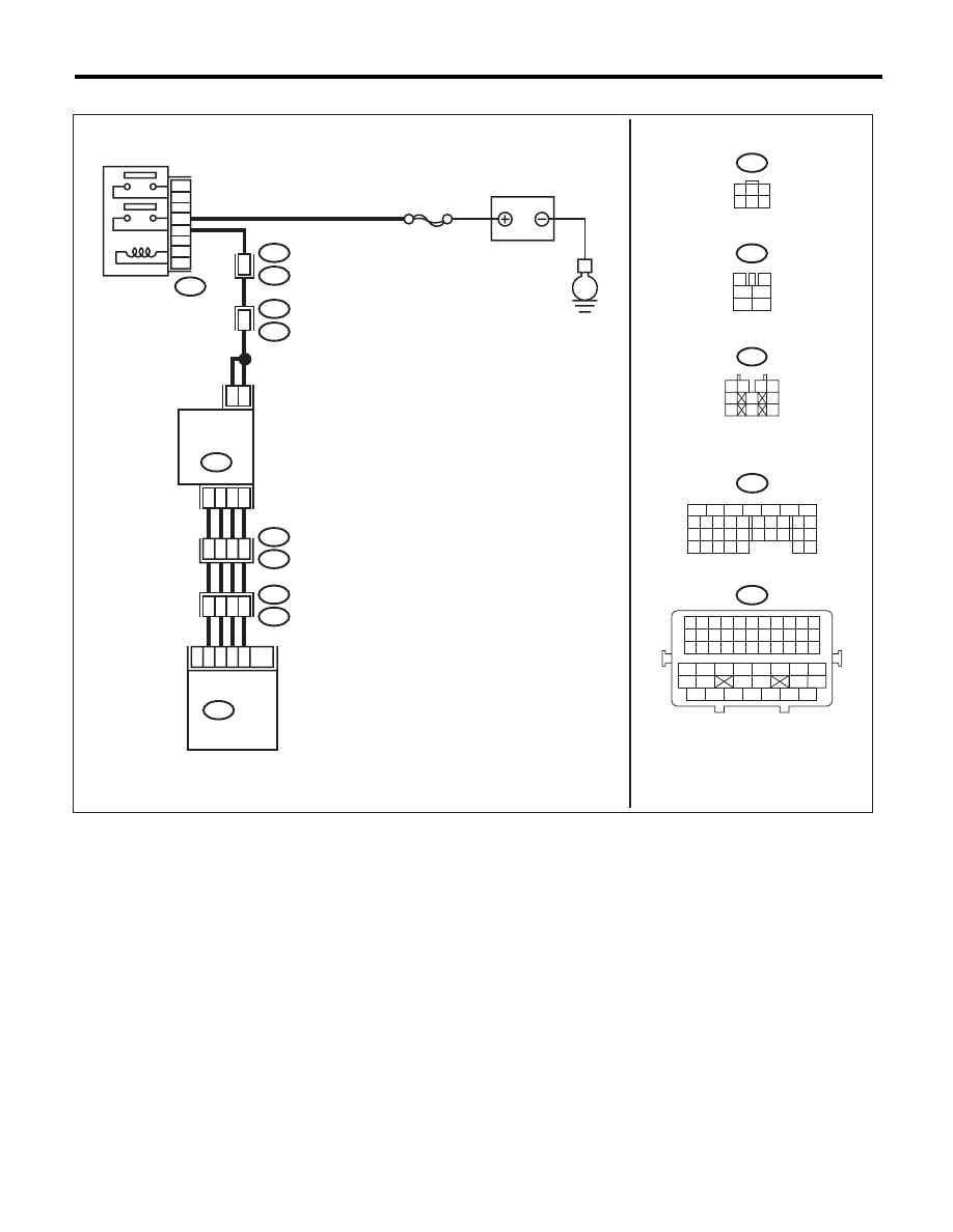
WIRING DIAGRAM:
E
B47
E18
2
5
1
4
3
6
B21
E2
E76
E77
48
3
4
7
6
SBF-7
B134
ECM
B47
3
4
1
2
5
6
5
6
7
8
2
1
9
4
3
10
24
22 23
25
11 12 13 14 15
26 27
28
16 17
18 19 20 21
33 34
29
32
30 31
B134
10
E76
E77
21
32
33
22
B21
E2
E18
1
3
4 5 6
2
1 2
3 4
5
6
7
8
9
10
E77
MAIN RELAY
BATTERY
EGR VALVE
6
4
9
10
8
20
EN-06877
B21
1 2 3 4 5 6 7 8 9 10 11
12 13 14 15 16 17 18 19 20 21 22
23 24 25 26 27 28 29 30 31 32 33
34
35
42
43
36
37
38
39
48
49
50
51
52
53
54
40
41
44
45
46
47