Subaru Legacy IV (2008 year). Manual - part 561
EN(H6DO)(diag)-217
Diagnostic Procedure with Diagnostic Trouble Code (DTC)
ENGINE (DIAGNOSTICS)
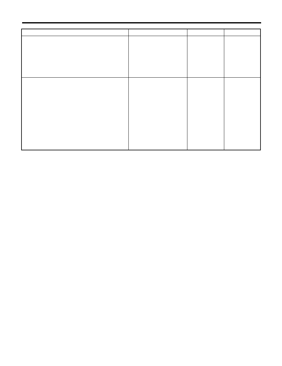
Step
Check
Yes
No
1
CHECK HARNESS BETWEEN ECM AND
KNOCK SENSOR.
1) Turn the ignition switch to OFF.
2) Disconnect the connectors from ECM.
3) Measure the resistance between ECM con-
nectors.
Connector & terminal
(B134) No. 15 — (B134) No. 29:
Is the resistance 600 k
: or
more?
Go to step 2.
Repair the poor
contact of ECM
connector.
2
CHECK KNOCK SENSOR.
1) Disconnect the connector from knock sen-
sor.
2) Measure the resistance between knock
sensor terminals.
Terminals
No. 1 — No. 2:
Is the resistance 600 k
: or
more?
Replace the knock
sensor. <Ref. to
FU(H6DO)-23,
Knock Sensor.>
Repair the harness
and connector.
NOTE:
In this case, repair
the following item:
• Open circuit of
harness between
ECM and knock
sensor
• Poor contact of
the knock sensor
connector
• Poor contact of
coupling connector