Subaru Legacy IV (2008 year). Manual - part 520


  Index      Subaru     Subaru Legacy IV - service repair manual 2008 year


Search            


Content   ..  518  519  520  521   ..


Subaru Legacy IV (2008 year). Manual - part 520


EN(H6DO)(diag)-53

Compulsory Valve Operation Check Mode

ENGINE (DIAGNOSTICS)

14.Compulsory Valve Operation 

Check Mode

A: OPERATION

1) Prepare the Subaru Select Monitor kit. <Ref. to
EN(H6DO)(diag)-7, PREPARATION TOOL, Gen-
eral Description.>

2) Prepare PC with Subaru Select Monitor in-
stalled.
3) Connect the USB cable between SDI (Subaru
Diagnosis Interface) and USB port on the personal
computer (dedicated port for the Subaru Select
Monitor).

NOTE:
The dedicated port for the Subaru Select Monitor
means the USB port which was used to install the
Subaru Select Monitor.
4) Connect the diagnosis cable to SDI.
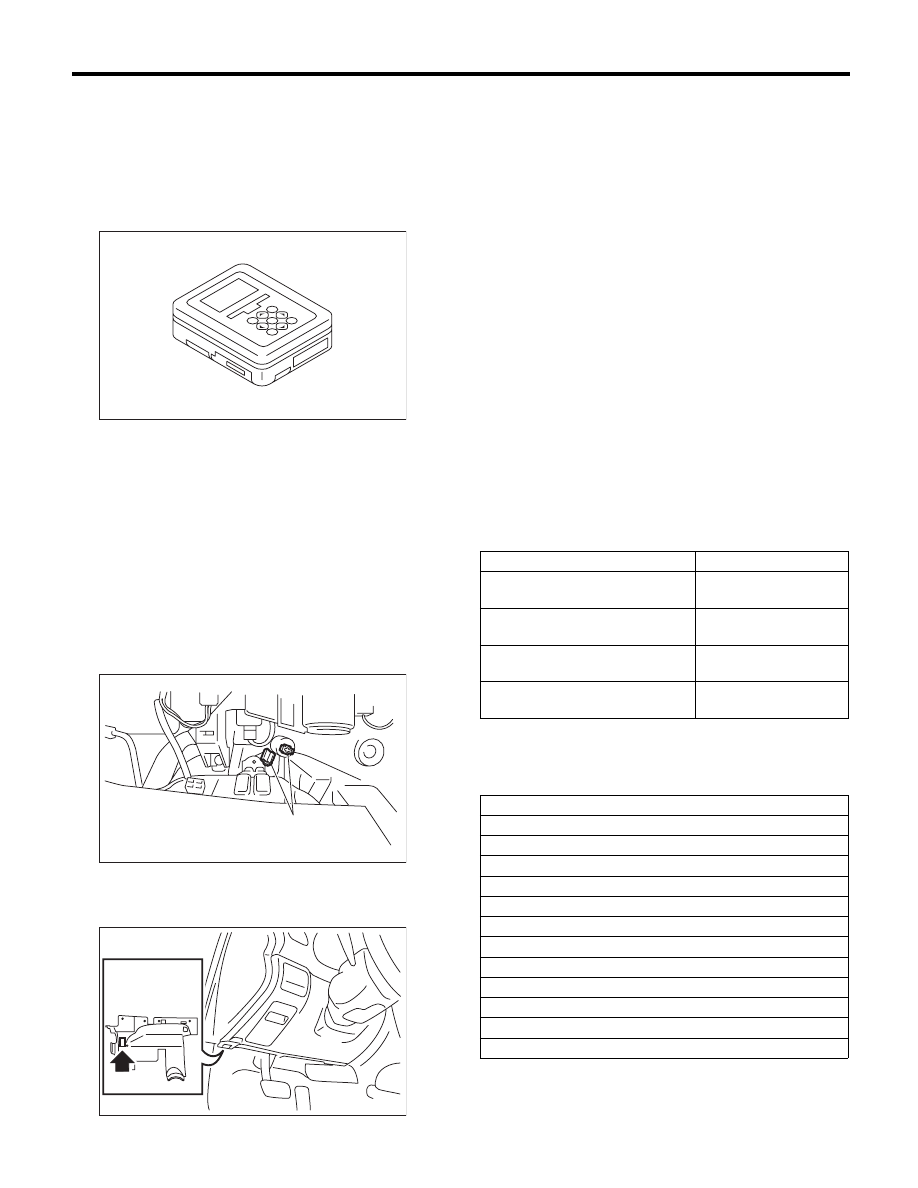
5) Connect the delivery (test) mode connector (A)
located under the glove box.

6) Connect SDI to data link connector located in the
lower portion of the instrument panel (on the driv-
er’s side).

CAUTION:
Do not connect the scan tools except for Suba-
ru Select Monitor and general scan tool.
7) Start the PC.
8) Turn the ignition switch to ON (engine OFF) and
run the “PC application for Subaru Select Monitor”.
9) On the «Main Menu» display screen, select the
{Each System Check}.
10) On the «System Selection Menu» display
screen, select the {Engine Control System}.
11) Click the [OK] button after the information of
engine type has been displayed.
12) On the «Engine Diagnosis» display screen, se-
lect the {System Operation Check Mode}.
13) On the «System Operation Check Mode» dis-
play, select the {Actuator ON/OFF Operation}.
14) Select the desired actuator on the «Actuator
ON/OFF Operation» display screen and click the
[Next] button.
15) Clicking the [End] button completes the com-
pulsory valve operation check mode. The display
will then return to the «Actuator ON/OFF Opera-
tion» screen.
• A list of the support data is shown in the following
table.

NOTE:

• The following parts will be displayed but not
functional.

• For detailed operation procedures, refer to the
“PC application help for Subaru Select Monitor”.

EN-05692

(A)

EN-02424

EN-02533

Description

Display

Compulsory fuel pump relay oper-
ation check

Fuel Pump Relay

Compulsory purge control sole-
noid valve operation check

CPC Solenoid Valve

Compulsory radiator fan relay 
operation check

Radiator Fan Relay

Compulsory air conditioning relay 
operation check

A/C Compressor Relay

Display

EGR Solenoid Valve

ASV Solenoid Valve

PCV Solenoid Valve

Vent. Solenoid Valve

FICD Solenoid

Pressure Switching Sol.1

Pressure Switching Sol.2

AAI Solenoid Valve

Tank Sensor Cntl Valve

Turbocharger Wastegate Solenoid

EXH. Bypass Control Permit Flag

Secondary Air Combi Valve 1

EN(H6DO)(diag)-54

System Operation Check Mode

ENGINE (DIAGNOSTICS)

15.System Operation Check 

Mode

A: OPERATION

1) Prepare the Subaru Select Monitor kit. <Ref. to
EN(H6DO)(diag)-7, PREPARATION TOOL, Gen-
eral Description.>

2) Prepare PC with Subaru Select Monitor in-
stalled.
3) Connect the USB cable between SDI (Subaru
Diagnosis Interface) and USB port on the personal
computer (dedicated port for the Subaru Select
Monitor).

NOTE:
The dedicated port for the Subaru Select Monitor
means the USB port which was used to install the
Subaru Select Monitor.
4) Connect the diagnosis cable to SDI.
5) Connect SDI to data link connector located in the
lower portion of the instrument panel (on the driv-
er’s side).

CAUTION:
Do not connect the scan tools except for Suba-
ru Select Monitor and general scan tool.
6) Start the PC.
7) Turn the ignition switch to ON (engine OFF) and
run the “PC application for Subaru Select Monitor”.
8) On the «Main Menu» display screen, select the
{Each System Check}.
9) On the «System Selection Menu» display
screen, select the {Engine Control System}.
10) Click the [OK] button after the information of
engine type has been displayed.

11) On the «Engine Diagnosis» display screen, se-
lect the {System Operation Check Mode}.
12) The following items are displayed on the moni-
tor.

1. FUEL PUMP CONTROL 
(OFF OPERATION)

CAUTION:
After executing the system operation check
mode, execute the Clear Memory Mode. <Ref. to
EN(H6DO)(diag)-52, OPERATION, Clear Memo-
ry Mode.>
1) On the «System Operation Check Mode» dis-
play screen, select the {Fuel Pump Control}.
2) On the «Fuel Pump Control» display screen, se-
lect the {OFF Drive}.
3) On the «Start the Engine» display screen, start
the engine and click the [OK] button.
4) On the «OFF Drive» display screen, click the
[Execution] button and execute the OFF drive.
5) Click the [Cancel] button to stop the OFF drive.
6) Click the [

 Exit] button to end the OFF drive.

The screen will return to the «Fuel Pump Control»
screen.

NOTE:
For detailed operation procedures, refer to the “PC
application help for Subaru Select Monitor”.

2. FUEL PUMP CONTROL 
(ON/OFF OPERATION)

CAUTION:
After executing the system operation check
mode, execute the Clear Memory Mode. <Ref. to
EN(H6DO)(diag)-52, OPERATION, Clear Memo-
ry Mode.>
1) On the «System Operation Check Mode» dis-
play screen, select the {Fuel Pump Control}.
2) On the «Fuel Pump Control» display screen, se-
lect the {ON/OFF Dr.}.
3) On the «Turn Ignition Switch ON with Engine
OFF» display screen, turn the ignition switch to ON
and click the [OK] button.
4) On the «ON/OFF Dr.» display screen, click the
[Execution] button and execute the ON/OFF drive.
5) Click the [Cancel] button to stop the ON/OFF
drive.

EN-05692

EN-02097

Display

Actuator ON/OFF Operation

Immobilizer System

Fuel Pump Control

Fixed Idle Ignition Timing

Idle Speed Control

Injector Control

EGR Valve Control

EN(H6DO)(diag)-55

System Operation Check Mode

ENGINE (DIAGNOSTICS)

6) Click the [

 Exit] button to end the ON/OFF

drive. The screen will return to the «Fuel Pump
Control» screen.

NOTE:
For detailed operation procedures, refer to the “PC
application help for Subaru Select Monitor”.

3. IDLING IGNITION TIMING FIXED

CAUTION:
After executing the system operation check
mode, execute the Clear Memory Mode. <Ref. to
EN(H6DO)(diag)-52, OPERATION, Clear Memo-
ry Mode.>
1) On the «System Operation Check Mode» dis-
play screen, select the {Fixed Idle Ignition Timing}.
2) On the «Start the Engine» display screen, start
the engine and click the [OK] button.
3) On the «Fixed Idle Ignition Timing» display
screen, click the [Execution] button and execute
the idling ignition timing fixed.
4) Click the [Cancel] button to stop the idling igni-
tion timing fixed.
5) Click the [

 Exit] button to end the idling ignition

timing fixed. The display will then return to the
«System Operation Check Mode» screen.

NOTE:
For detailed operation procedures, refer to the “PC
application help for Subaru Select Monitor”.

4. IDLE SPEED CONTROL

CAUTION:
After executing the system operation check
mode, execute the Clear Memory Mode. <Ref. to
EN(H6DO)(diag)-52, OPERATION, Clear Memo-
ry Mode.>
1) On the «System Operation Check Mode» dis-
play screen, select the {Idle Speed Control}.
2) On the «Start the Engine» display screen, start
the engine and click the [OK] button.
3) In the «Idle Speed Control» display screen, click
the [

] button or the [

] button to change the set-

ting values, then click the [OK] button.
Setting is possible in a range between 500 rpm —
2,000 rpm, in increments of 50 rpm. However, the
engine speed that can actually be controlled will
vary depending on the vehicle.
4) Click the [Cancel] button to stop the idle speed
control.
5) Click the [

 Exit] button to end the idle speed

control. The display will then return to the «System
Operation Check Mode» screen.

NOTE:
For detailed operation procedures, refer to the “PC
application help for Subaru Select Monitor”.

5. INJECTOR CONTROL 
(INJECTION STOP MODE)

CAUTION:
After executing the system operation check
mode, execute the Clear Memory Mode. <Ref. to
EN(H6DO)(diag)-52, OPERATION, Clear Memo-
ry Mode.>
1) On the «System Operation Check Mode» dis-
play screen, select the {Injector Control}.
2) On the «Injector Control» display screen, select
the {Injection Stop Mode}.
3) On the «Injection Stop Mode» display screen,
select the fuel injector to be stopped.
4) On the «Start the Engine» display screen, start
the engine and click the [OK] button.
5) On the «Fuel Injector #» display screen, click the
[Execution] button and execute the injection stop
mode.
6) Click the [Cancel] button to stop the injection
stop mode.
7) Click the [

 Exit] button to return the «Injection

Stop Mode» display screen.
8) On the «Injection Stop Mode» display screen, click
the [Return] button to end the «Injection Stop Mode».
The screen will return to the «Injector Control» screen.

NOTE:
For detailed operation procedures, refer to the “PC
application help for Subaru Select Monitor”.

6. INJECTOR CONTROL 
(INJECTION QUANTITY CONTROL)

CAUTION:
After executing the system operation check
mode, execute the Clear Memory Mode. <Ref. to
EN(H6DO)(diag)-52, OPERATION, Clear Memo-
ry Mode.>
1) On the «System Operation Check Mode» dis-
play screen, select the {Injector Control}.
2) On the «Injector Control» display screen, select
the {Injection Quantity Control}.
3) On the «Start the Engine» display screen, start
the engine and click the [OK] button.
4) In the «Injection Quantity Control» display screen,
click the [

] button or the [

] button to change the

setting values, then click the [OK] button.
Setting is possible in a range between 0 — 20%, in
increments of 1%.
5) Click the [Cancel] button to stop the injection
quantity control.
6) Click the [

 Exit] button to end the injection

quantity control. The screen will return to the «In-
jector Control» screen.

NOTE:
For detailed operation procedures, refer to the “PC
application help for Subaru Select Monitor”.

EN(H6DO)(diag)-56

System Operation Check Mode

ENGINE (DIAGNOSTICS)

7. EGR VALVE CONTROL

CAUTION:
After executing the system operation check
mode, execute the Clear Memory Mode. <Ref. to
EN(H6DO)(diag)-52, OPERATION, Clear Memo-
ry Mode.>
1) On the «System Operation Check Mode» dis-
play screen, select the {EGR Valve Control}.
2) On the «Start the Engine» display screen, start
the engine and click the [OK] button.
3) In the «EGR Valve Control» display screen, click
the [

] button or the [

] button to change the set-

ting values, then click the [OK] button.
Setting is possible in increments of 1 STEP. How-
ever, the STEP number that can actually be con-
trolled will vary depending on the vehicle.
4) Click the [Cancel] button to stop the EGR valve
control.
5) Click the [

 Exit] button to end the EGR valve

control. The display will then return to the «System
Operation Check Mode» screen.

NOTE:
For detailed operation procedures, refer to the “PC
application help for Subaru Select Monitor”.


Content   ..  518  519  520  521   ..