Subaru Legacy IV (2008 year). Manual - part 488


  Index      Subaru     Subaru Legacy IV - service repair manual 2008 year


Search            


Content   ..  486  487  488  489   ..


Subaru Legacy IV (2008 year). Manual - part 488


ME(H6DO)-78

Cylinder Block

MECHANICAL

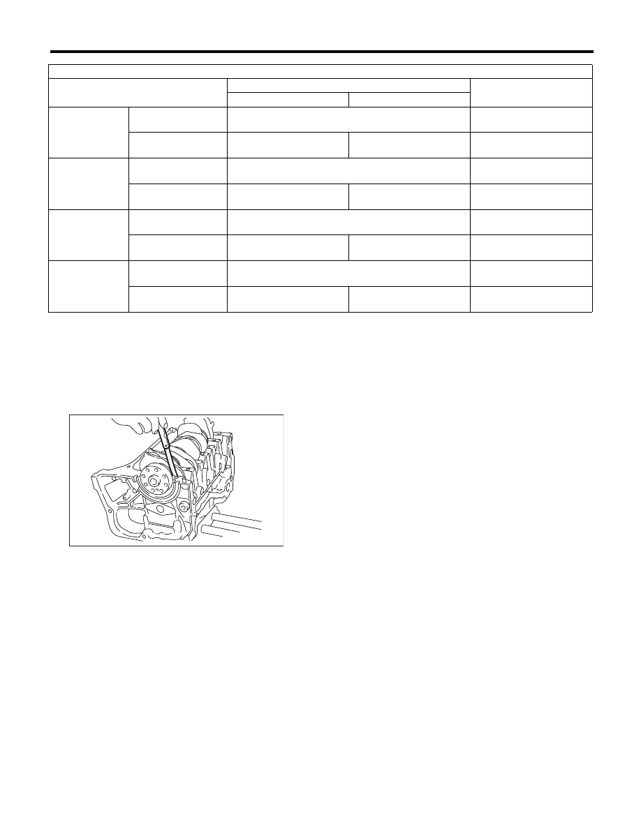
4) Measure the thrust clearance of crankshaft at
center bearing by using thickness gauge. If the
thrust clearance is not within the standard, replace
the bearing.

Crankshaft thrust clearance:

Standard

0.030 — 0.115 mm (0.0012 — 0.0045 in)

5) Inspect individual crankshaft bearings for signs
of flaking, seizure, melting and wear.
6) Measure the oil clearance on each crankshaft
bearing using plastigauge. If the measured value is
out of standard, replace the defective bearing with
an undersize one, and replace or recondition the
crankshaft as necessary.

Crankshaft oil clearance:

Standard

0.010 — 0.030 mm (0.0004 — 0.0012 in)

Unit: mm (in)


Crank journal diameter

Crank pin outer diameter

#1, #3, #5, #7

#2, #4, #6

Standard

Journal O.D.

63.992 — 64.008

(2.5194 — 2.5200)

51.984 — 52.000

(2.0466 — 2.0472)

Bearing size
(Thickness at center)

1.992 — 2.005

(0.0784 — 0.0789)

1.996 — 2.009

(0.0786 — 0.0791)

1.490 — 1.506

(0.0587 — 0.0593)

0.03 (0.0012)
undersize

Journal O.D.

63.962 — 63.978

(2.5182 — 2.5188)

51.954 — 51.970

(2.0454 — 2.0461)

Bearing size
(Thickness at center)

2.011 — 2.014

(0.0792 — 0.0793)

2.015 — 2.018

(0.0793 — 0.0794)

1.509 — 1.513

(0.0594 — 0.0596)

0.05 (0.0020)
undersize

Journal O.D.

63.942 — 63.958

(2.5174 — 2.5180)

51.934 — 51.950

(2.0446 — 2.0453)

Bearing size
(Thickness at center)

2.021 — 2.024

(0.0796 — 0.0797)

2.025 — 2.028

(0.0797 — 0.0798)

1.519 — 1.523

(0.0598 — 0.0600)

0.25 (0.0098)
undersize

Journal O.D.

63.742 — 63.758

(2.5095 — 2.5102)

51.734 — 51.750

(2.0368 — 2.0374)

Bearing size
(Thickness at center)

2.121 — 2.124

(0.0835 — 0.0836)

2.125 — 2.128

(0.0837 — 0.0838)

1.619 — 1.623

(0.0637 — 0.0639)

ME-00600

ME(H6DO)-79

Oil Flow Control Solenoid Valve

MECHANICAL

22.Oil Flow Control Solenoid 

Valve

A: REMOVAL

Oil flow control solenoid valve is a unit with cam-
shaft cap. Refer to “Camshaft” for removal proce-
dures. <Ref. to ME(H6DO)-55, REMOVAL,
Camshaft.>

B: INSTALLATION

Install in the reverse order of removal.

ME(H6DO)-80

Oil Switching Solenoid Valve

MECHANICAL

23.Oil Switching Solenoid Valve

A: REMOVAL

1) Disconnect the ground cable from the battery.

2) Remove the air intake chamber. <Ref. to
IN(H6DO)-7, REMOVAL, Air Intake Chamber.>
3) Disconnect the connector from the oil switching
solenoid valve.

4) Remove the oil switching solenoid valve.
5) Remove the variable valve lift diagnosis oil pres-
sure switch. <Ref. to FU(H6DO)-30, REMOVAL,
Variable Valve Lift Diagnosis Oil Pressure Switch.>
6) Remove the oil temperature sensor. <Ref. to
FU(H6DO)-31, REMOVAL, Oil Temperature Sen-
sor.>
7) Remove the oil switching solenoid valve holder
from the cylinder head.

B: INSTALLATION

1) Install the oil switching solenoid valve holder.

NOTE:
Use a new gasket.

(1) Temporarily tighten the bolts by tightening
torque of 5 — 10 N·m (0.5 — 1.0 kgf-m, 3.7 —
7.4 ft-lb) in order shown in the figure.
(2) Tighten the bolts by tightening torque of
10

r0.5 N·m (1.0r0.05 kgf-m, 7.4r0.37 ft-lb) in

order shown in the figure.

2) Install the oil temperature sensor. <Ref. to
FU(H6DO)-31, INSTALLATION, Oil Temperature
Sensor.>
3) Install the variable valve lift diagnosis oil pres-
sure switch. <Ref. to FU(H6DO)-30, INSTALLA-
TION, Variable Valve Lift Diagnosis Oil Pressure
Switch.>
4) Install the oil switching solenoid valve.
5) Connect the connector to the oil switching sole-
noid valve.

6) Install the air intake chamber. <Ref. to IN(H6DO)-
7, INSTALLATION, Air Intake Chamber.>
7) Connect the ground cable to battery.

IN-00203

ME-02071

ME-02072

ME-02073

(2)

(1)

(5)

(4)

(3)

ME-02071

IN-00203

ME(H6DO)-81

Intake and Exhaust Valve

MECHANICAL

24.Intake and Exhaust Valve

A: SPECIFICATION

Refer to “Cylinder Head” for removal and installa-
tion procedures of the intake and exhaust valves.
<Ref. to ME(H6DO)-59, REMOVAL, Cylinder
Head.> <Ref. to ME(H6DO)-59, INSTALLATION,
Cylinder Head.>


Content   ..  486  487  488  489   ..