Subaru Legacy IV (2008 year). Manual - part 486


  Index      Subaru     Subaru Legacy IV - service repair manual 2008 year


Search            


Content   ..  484  485  486  487   ..


Subaru Legacy IV (2008 year). Manual - part 486


ME(H6DO)-70

Cylinder Block

MECHANICAL

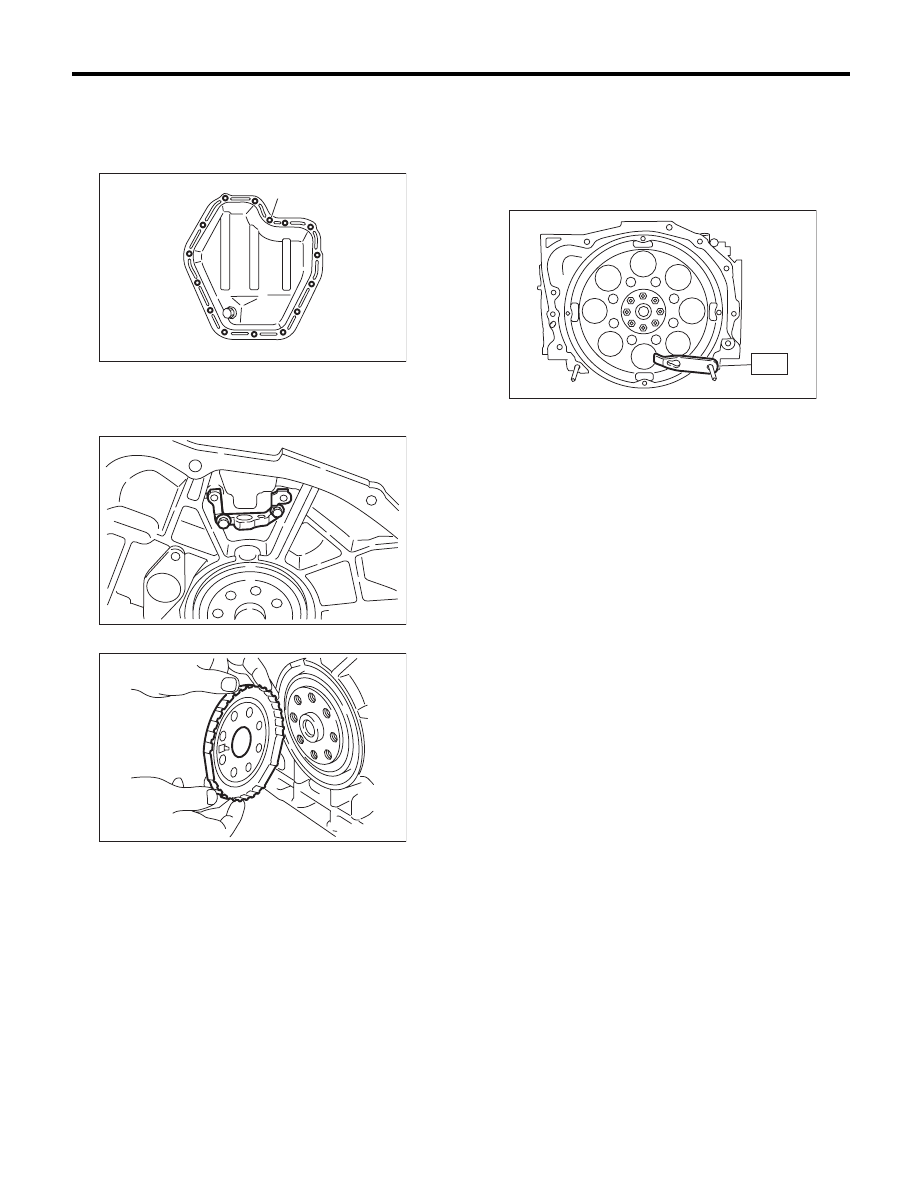
24) Tighten the oil pan lower installing bolts in the
numerical order as shown in the figure.

Tightening torque:

6.4 N·m (0.7 kgf-m, 4.7 ft-lb)

25) Attach the crankshaft position sensor holder.

Tightening torque:

6.4 N·m (0.7 kgf-m, 4.7 ft-lb)

26) Install the crankshaft sensor plate.

27) Use the ST to lock the crankshaft, and install
the drive plate.
ST1

498497100

CRANKSHAFT STOPPER

ST2

499057000

TORX PLUS

®

Tightening torque:

81 N·m (8.3 kgf-m, 59.7 ft-lb)

28) Install the cylinder head. <Ref. to ME(H6DO)-
59, INSTALLATION, Cylinder Head.>
29) Install the camshaft. <Ref. to ME(H6DO)-56,
INSTALLATION, Camshaft.>
30) Install the rear chain cover. <Ref. to
ME(H6DO)-53, INSTALLATION, Rear Chain Cov-
er.>
31) Install the crank sprocket. <Ref. to ME(H6DO)-
52, INSTALLATION, Crank Sprocket.>
32) Install the cam sprocket. <Ref. to ME(H6DO)-
51, INSTALLATION, Cam Sprocket.>
33) Install the timing chain assembly. <Ref. to
ME(H6DO)-47, INSTALLATION, Timing Chain As-
sembly.>
34) Install the front chain cover. <Ref. to
ME(H6DO)-44, INSTALLATION, Front Chain Cov-
er.>
35) Install the crank pulley. <Ref. to ME(H6DO)-43,
INSTALLATION, Crank Pulley.>
36) Install the V-belts. <Ref. to ME(H6DO)-42, IN-
STALLATION, V-belt.>

(1)

(2)

(3)

(4)

(5)

(6)

(7)

(8)

(9)

(10)

(11)

(12)

(13)

(14)

(15)

ME-00582

ME-00559

ME-00558

ST

ME-00557

ME(H6DO)-71

Cylinder Block

MECHANICAL

C: DISASSEMBLY

1) Remove the connecting rod cap.
2) Remove the connecting rod bearing.

NOTE:
Arrange the removed connecting rod, connecting
rod cap and bearing in order, to prevent confusion.
3) Remove the piston rings using piston ring ex-
pander.
4) Remove the oil ring by hand.

NOTE:
Arrange the removed piston rings in proper order,
to prevent confusion.
5) Remove the snap ring.

(1)

Connecting rod cap

(4)

Second ring

(6)

Snap ring

(2)

Connecting rod bearing

(5)

Oil ring

(7)

Connecting rod

(3)

Top 

ring


(1)

(1)

(2)

(2)

(7)

(2)

(7)

(3)

(3)

(4)

(4)

(5)

(5)

(6)

(6)

ME-03955

ME(H6DO)-72

Cylinder Block

MECHANICAL

D: ASSEMBLY

1) Apply oil to the surface of the connecting rod
bearings, and install the bearings on the connect-
ing rods and connecting rod caps.
2) Position each connecting rod with the marking
side facing forward.
3) Install the connecting rod cap. Make sure the ar-
row mark on connecting rod cap facing front during
installation.

CAUTION:
• Each connecting rod has its own mating cap.
Make sure that they are assembled correctly by
checking their matching number.
• When tightening the connecting rod bolts,
apply oil on the threads and flange end.

Tightening torque:

53 N·m (5.4 kgf-m, 39.1 ft-lb)

4) Install the oil ring spacer, upper rail and lower rail
by hand.
5) Install the second ring and top ring using piston
ring expander.

(1)

Connecting rod cap

(5)

Oil ring

Tightening torque:N·m (kgf-m, ft-lb)

(2)

Connecting rod bearing

(6)

Snap ring

T: 53 (5.4, 39.1)

(3)

Top ring

(7)

Connecting rod


(4)

Second 

ring


(1)

(1)

(2)

(2)

(2)

(7)

(3)

(4)

(5)

(7)

(3)

(4)

(5)

(6)

(6)

T

T

ME-02459

ME(H6DO)-73

Cylinder Block

MECHANICAL

E: INSPECTION

1. CYLINDER BLOCK

1) Check for cracks or damage. Use liquid pene-
trant tester on the important sections to check for
fissures. Check that there are no marks of gas leak-
ing or water leaking on gasket installing surface.
2) Check the oil passages for clogging.
3) Inspect the cylinder block surface that mates
with cylinder head for warping by using a straight
edge. If the warping exceeds the limit, replace the
cylinder block.

Warping limit:

0.02 mm (0.0008 in)

Standard height of cylinder block:

202 mm (7.95 in)

2. CYLINDER AND PISTON

1) The cylinder bore size is stamped on the front
upper face of the cylinder block.

NOTE:
• Measurement should be performed at a temper-
ature of 20°C (68°F).
• Standard sized pistons are classified into two
grades, “A” and “B”. These grades should be used
as guide lines in selecting a standard piston.

Standard diameter:

A: 89.205 — 89.215 mm (3.5120 — 3.5124 in)
B: 89.195 — 89.205 mm (3.5116 — 3.5120 in)

2) How to measure the inner diameter of each cyl-
inder:
Measure the inner diameter of each cylinder in both
the thrust and piston pin directions at the heights as
shown in the figure, using a cylinder bore gauge.

NOTE:
Measurement should be performed at a tempera-
ture of 20°C (68°F).

Cylindricality:

Standard

0.030 mm (0.0012 in)

Out-of-roundness:

Standard

0.010 mm (0.0004 in)

3) When the piston is to be replaced due to general
or cylinder wear, determine a suitable sized piston
by measuring the piston clearance.

(A) Main journal size mark

(B) Cylinder bore size mark

(C) Cylinder block (RH) – (LH) combination mark

#7

#6

#5

#2

#1

#4

#3

#6
#5
#4
#3
#2
#1

BBB

2

4
2B

A

B

4

(A)

(B)

(C)

ME-00585

(A) Piston pin direction

(B) Thrust direction

H1: 10 mm (0.39 in)

H2: 45 mm (1.77 in)

H3: 80 mm (3.15 in)

ME-00586

H1

H2

H3

Unit: mm (in)

(B)

(A)


Content   ..  484  485  486  487   ..