Subaru Legacy IV (2008 year). Manual - part 341
EN(H4DOTC)(diag)-185
Diagnostic Procedure with Diagnostic Trouble Code (DTC)
ENGINE (DIAGNOSTICS)
BA:DTC P0340 CAMSHAFT POSITION SENSOR “A” CIRCUIT (BANK 1 OR SINGLE
SENSOR)
DTC DETECTING CONDITION:
• Immediately at fault recognition
• GENERAL DESCRIPTION <Ref. to GD(H4DOTC)-92, DTC P0340 CAMSHAFT POSITION SENSOR “A”
CIRCUIT (BANK 1 OR SINGLE SENSOR), Diagnostic Trouble Code (DTC) Detecting Criteria.>
TROUBLE SYMPTOM:
• Engine stalls.
• Failure of engine to start
CAUTION:
After repair or replacement of faulty parts, perform Clear Memory Mode <Ref. to EN(H4DOTC)(diag)-
52, OPERATION, Clear Memory Mode.>, and Inspection Mode <Ref. to EN(H4DOTC)(diag)-43, PRO-
CEDURE, Inspection Mode.>.
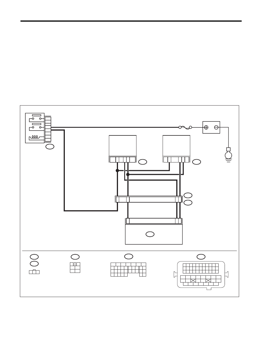
WIRING DIAGRAM:
EN-05677
5
6
7
8
2
1
9
4
3
10
24
22 23
25
11 12 13 14 15
26 27
28
16 17
18 19 20 21
33 34
29
32
30 31
B47
1
2
4
6
3
5
E
3
22
SBF-7
E35
E2
B21
2
E36
1
3
11
2
1
B134
3
4
1
2
5
6
E36
B47
1 2 3
B134
E35
21
B21
1 2 3 4
12 13 14 15
5 6 7 8
16 17 18 19
9 10 11
20 21 22
23 24 25 26 27 28 29 30 31 32 33
35
34
37
36
39
38
41
40
43
42
44
45
47
46
49
48
51
50
53
52
54
5
48
2
13
MAIN RELAY
BATTERY
INTAKE
CAMSHAFT
POSITION
SENSOR LH
INTAKE
CAMSHAFT
POSITION
SENSOR RH
ECM