Subaru Legacy IV (2008 year). Manual - part 230


  Index      Subaru     Subaru Legacy IV - service repair manual 2008 year


Search            


Content   ..  228  229  230  231   ..


Subaru Legacy IV (2008 year). Manual - part 230


FU(H4DOTC)-23

Intake Manifold

FUEL INJECTION (FUEL SYSTEMS)

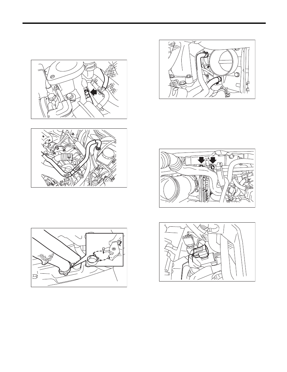
13) Connect the air control hose (A) to the waste-
gate actuator, and tighten the clamp that holds the
intake duct on the turbocharger.

Tightening torque:

3 N·m (0.3 kgf-m, 2.2 ft-lb)

14) Connect the brake booster vacuum hose.

15) Connect the PCV hose to the rocker cover.

NOTE:
Use a new clamp for the PCV hose clamp, fit the
cut out in the ST with the protrusion on the clamp as
shown in the figure, and lock the clamp.
ST

18353AA000

CLAMP PLIERS

16) Connect the engine coolant hoses to throttle
body.

17) Install the duct to the throttle body.

Tightening torque:

3 N·m (0.3 kgf-m, 2.2 ft-lb)

18) Attach the bolts which secure the air by-pass
pipe and PCV pipe to the intake manifold.

Tightening torque:

6.5 N·m (0.7 kgf-m, 4.8 ft-lb)

19) Attach the connector to the PCV hose assem-
bly.

(A)

IN-02499

ME-03898

FU-03116

FU-03814

FU-03028

FU-03899

FU(H4DOTC)-24

Intake Manifold

FUEL INJECTION (FUEL SYSTEMS)

20) Connect the vacuum hose (A) and the connec-
tor (B) to the PCV hose assembly.

21) Install the A/C pressure hoses. <Ref. to AC-40,
INSTALLATION, Hose and Pipe.>
22) Install the coolant filler tank. <Ref. to
CO(H4DOTC)-30, INSTALLATION, Coolant Filler
Tank.>
23) Install the generator. <Ref. to SC(H4SO)-14,
INSTALLATION, Generator.>
24) Install the intercooler. <Ref. to IN(H4DOTC)-
13, INSTALLATION, Intercooler.>
25) Install the air intake duct and air cleaner case.
<Ref. to IN(H4DOTC)-8, INSTALLATION, Air
Cleaner Case.> <Ref. to IN(H4DOTC)-9, INSTAL-
LATION, Air Intake Duct.>
26) Install the battery. <Ref. to SC(H4SO)-20, IN-
STALLATION, Battery.>
27) Lift up the vehicle.
28) Install the under cover.
29) Lower the vehicle.
30) Fill engine coolant. <Ref. to CO(H4DOTC)-14,
FILLING OF ENGINE COOLANT, REPLACE-
MENT, Engine Coolant.>
31) Charge the A/C system with refrigerant. <Ref.
to AC-23, PROCEDURE, Refrigerant Charging
Procedure.>
32) Install the collector cover.

C: DISASSEMBLY

1) Remove the engine ground terminal from the
fuel pipe protector LH, and remove the fuel pipe
protector LH from the intake manifold.

2) Remove the fuel pipe protector RH from the in-
take manifold.

3) Disconnect the evaporation hose and the con-
nector from the purge control solenoid valve 1, and
remove the purge control solenoid valve 1 from the
intake manifold.

4) Disconnect the filter assembly.

FU-03898

(B)

(A)

FU-03086

FU-03087

FU-04030

FU-03030

FU(H4DOTC)-25

Intake Manifold

FUEL INJECTION (FUEL SYSTEMS)

5) Remove the solenoid valve bracket assembly
from the intake manifold, and disconnect the con-
nector from the wastegate control solenoid valve,
manifold absolute pressure sensor and purge con-
trol solenoid valve 2.

6) Disconnect the evaporation hose of the purge
control solenoid valve 2 from the intake duct and
fuel pipe assembly.
7) Disconnect the connectors from the throttle posi-
tion sensor.

8) Remove the throttle body from the intake mani-
fold.

9) Disconnect the connector from the fuel injector
and the tumble generator valve assembly.

10) Remove the PCV pipe (A), harness assembly
(B) and intake duct (C) from the intake manifold.

11) Remove the bolt which secures the fuel injector
pipe LH onto the front side of intake manifold, and
disconnect the pressure regulator vacuum hose
from the intake manifold.

EC-00219

FU-03463

FU-03815

FU-03088

FU-03033

(C)

(A)

(B)

FU-04031

FU(H4DOTC)-26

Intake Manifold

FUEL INJECTION (FUEL SYSTEMS)

12) Remove the bolt which holds fuel injector pipe
onto intake manifold.
• RH side

• LH  side

13) Remove the fuel injector.
• RH side

• LH  side

14) Remove the bolt which holds fuel injector pipe
onto intake manifold.

15) Remove the bolt which secures fuel injector
pipe RH onto the lower side of the intake manifold.

16) Loosen the clamp which holds the fuel hose to
the fuel injector pipe, and then disconnect the fuel
hose from pipe.

17) Remove the fuel injector pipe.
18) Remove the tumble generator valve assembly
from the intake manifold.

FU-03089

FU-03090

FU-03094

FU-03091

FU-03109

FU-03110

FU-03111

FU-03039


Content   ..  228  229  230  231   ..