Subaru Legacy IV (2008 year). Manual - part 229


  Index      Subaru     Subaru Legacy IV - service repair manual 2008 year


Search            


Content   ..  227  228  229  230   ..


Subaru Legacy IV (2008 year). Manual - part 229


FU(H4DOTC)-19

Intake Manifold

FUEL INJECTION (FUEL SYSTEMS)

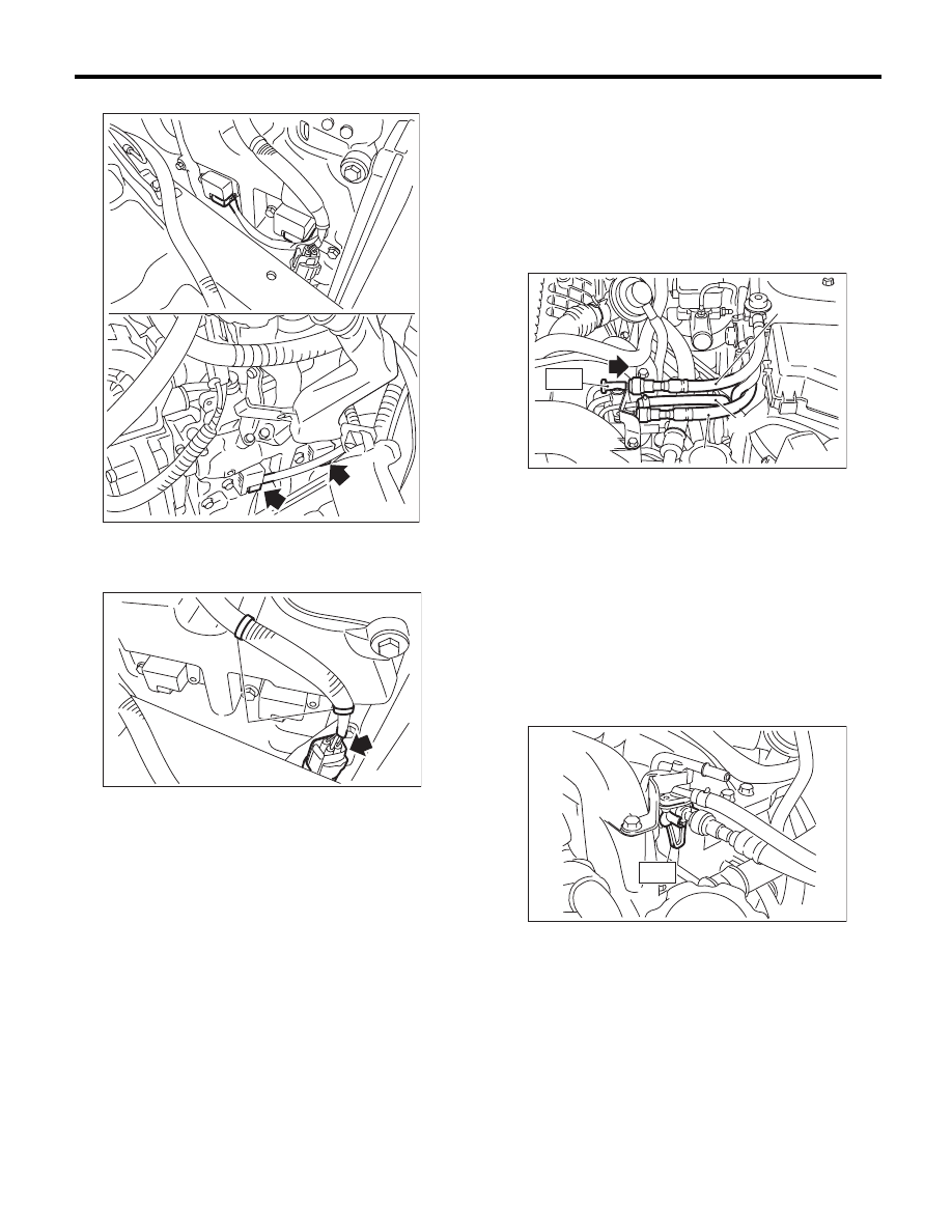
32) Disconnect the connector from ignition coil.

33) Disconnect the connector from the front oxygen
(A/F) sensor, and remove the engine harness fixed
by clip (A) from the rocker cover. (right side only)

34) Attach ST to the fuel delivery pipe and push ST
in the direction of arrow mark to disconnect the fuel
delivery hose.
ST

42099AE000

QUICK CONNECTOR 
RELEASE

CAUTION:
• Be careful not to spill fuel.
• Catch the fuel from hoses using a container
or cloth.

35) Disconnect the fuel return hose using the ST.
ST

18371AA000

CONNECTOR REMOVER

CAUTION:
• Be careful not to spill fuel.
• Catch the fuel from hoses using a container
or cloth.

(1) Attach ST to the fuel return pipe as shown in
the figure.

FU-04003

FU-03993

(A)

(A) Fuel delivery hose

(B) Fuel return hose

(C) Evaporation hose

FU-03411

(A)

(B)

ST

(C)

FU-03092

ST

FU(H4DOTC)-20

Intake Manifold

FUEL INJECTION (FUEL SYSTEMS)

(2) Insert the front side of ST into the quick con-
nector.

(3) Insert the back side of ST into the quick con-
nector and push ST in the direction of arrow
mark to disconnect the fuel return hose.

36) Remove the clip and disconnect the evapora-
tion hose from the fuel pipe.

37) Remove the bolts which hold the tumble gener-
ator valve assembly onto the cylinder head.

38) Remove the intake manifold.

B: INSTALLATION

1) Install the intake manifold onto cylinder heads.

NOTE:
Use a new gasket.

Tightening torque:

25 N·m (2.5 kgf-m, 18.4 ft-lb)

2) Connect the fuel delivery hose, fuel return hose,
and evaporation hose. <Ref. to FU(H4DOTC)-81,
INSTALLATION, Fuel Delivery, Return and Evapo-
ration Lines.>

NOTE:
If fuel hoses or clamps are damaged, replace them
with new parts.

FU-03113

ST

FU-03114

ST

FU-03105

FU-03085

(A) Fuel delivery hose

(B) Fuel return hose

(C) Evaporation hose

FU-03085

FU-03412

(A)

(B)

(C)

FU(H4DOTC)-21

Intake Manifold

FUEL INJECTION (FUEL SYSTEMS)

3) Connect the connector to the oil flow control so-
lenoid valve.

4) Connect the connector to the engine coolant
temperature sensor (A), oil pressure switch (B) and
crankshaft position sensor (C).

5) Connect the connector to the knock sensor.

6) Connect the connector to the power steering
pump switch.

7) Connect the connectors to camshaft position
sensor.

FU-03903

(A)

(B)

(C)

FU-00027

FU-03900

FU-03022

FU-03902

FU(H4DOTC)-22

Intake Manifold

FUEL INJECTION (FUEL SYSTEMS)

8) Connect the connector to the secondary air com-
bination valve.

9) Connect the connector from the front oxygen (A/
F) sensor, and install the engine harness with clip
(A) to the rocker cover. (right side only)

10) Connect the connector to the ignition coil.

11) Connect the air duct to the secondary air pump,
and install the air duct on the rocker cover.

Tightening torque:

9 N·m (0.9 kgf-m, 6.6 ft-lb)

12) Install the engine harness connector to engine
harness bracket, then connect the bulkhead har-
ness connector to the engine harness connector.

FU-03901

FU-03993

(A)

FU-04003

FU-03905

FU-02436


Content   ..  227  228  229  230   ..