Subaru Legacy IV (2008 year). Manual - part 164
EN(H4SO)(diag)-259
Diagnostic Procedure with Diagnostic Trouble Code (DTC)
ENGINE (DIAGNOSTICS)
CW:DTC P1560 BACK-UP VOLTAGE CIRCUIT MALFUNCTION
DTC DETECTING CONDITION:
• Immediately at fault recognition
• GENERAL DESCRIPTION <Ref. to GD(H4SO)-174, DTC P1560 BACK-UP VOLTAGE CIRCUIT MAL-
FUNCTION, Diagnostic Trouble Code (DTC) Detecting Criteria.>
CAUTION:
After repair or replacement of faulty parts, perform Clear Memory Mode <Ref. to EN(H4SO)(diag)-50,
OPERATION, Clear Memory Mode.>, and Inspection Mode <Ref. to EN(H4SO)(diag)-41, PROCEDURE,
Inspection Mode.>.
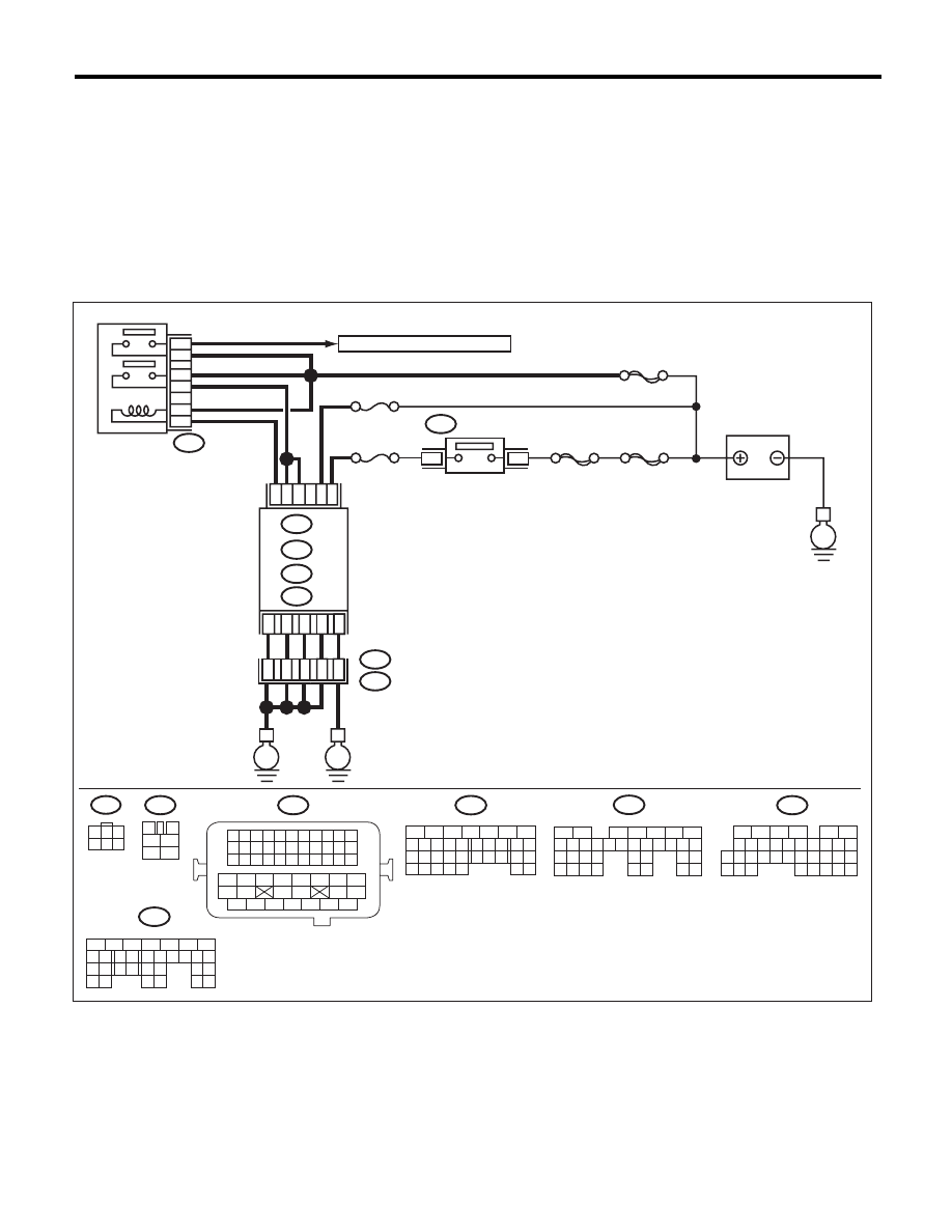
WIRING DIAGRAM:
EN-06831
SBF-6
MAIN SBF
SBF-7
B72
No. 12
B47
E2
B21
2
1
4
6
5
3
E
3
1
B134
B135
A:
D: B137
C: B136
B:
3
4
1
2
5
6
B47
No. 13
B134
5
6
7
8
2
1
9
4
3
10
24
22 23
25
11 12 13 14 15
26 27
28
16 17
18 19 20 21
33 34
29
32
30 31
B135
5
6
7
8
2
1
9
4
3
10
24
22 23
25
11 12 13 14 15
26 27
28
16 17 18 19
20 21
29 30 31
32 33
34 35
B137
5
6
7
8
2
1
9
4
3
10
22 23
11 12 13 14 15
24 25
26
16 17
18 19 20 21
27
28 29
30 31
B21
1 2 3 4
12 13 14 15
5 6 7 8
16 17 18 19
9 10 11
20 21 22
23 24 25 26 27 28 29 30 31 32 33
35
34
37
36
39
38
41
40
43
42
44
45
47
46
49
48
51
50
53
52
54
B72
1
3
4 5 6
2
A:
B:
D:
MAIN RELAY
ECM
TO IGNITION COIL & IGNITOR ASSY
BATTERY
IGNITION
SWITCH
A7
B2
C23
B19
A5
D2
D1
D3
B5
36
34
37
35
D7
52
16
10 11 12 13 14 15
25
24
30
9
8
7
17 18 19 20
28
21 22 23
29
32
31
1
2
3
4
5
6
27
26
33 34 35
B136
C:
E
E