Subaru Legacy IV (2008 year). Manual - part 159
EN(H4SO)(diag)-239
Diagnostic Procedure with Diagnostic Trouble Code (DTC)
ENGINE (DIAGNOSTICS)
CG:DTC P0852 NEUTRAL SWITCH INPUT CIRCUIT HIGH (MT MODEL)
DTC DETECTING CONDITION:
• Two consecutive driving cycles with fault
• GENERAL DESCRIPTION <Ref. to GD(H4SO)-155, DTC P0852 NEUTRAL SWITCH INPUT CIRCUIT
HIGH (MT MODEL), Diagnostic Trouble Code (DTC) Detecting Criteria.>
TROUBLE SYMPTOM:
Improper idling
CAUTION:
After repair or replacement of faulty parts, perform Clear Memory Mode <Ref. to EN(H4SO)(diag)-50,
OPERATION, Clear Memory Mode.>, and Inspection Mode <Ref. to EN(H4SO)(diag)-41, PROCEDURE,
Inspection Mode.>.
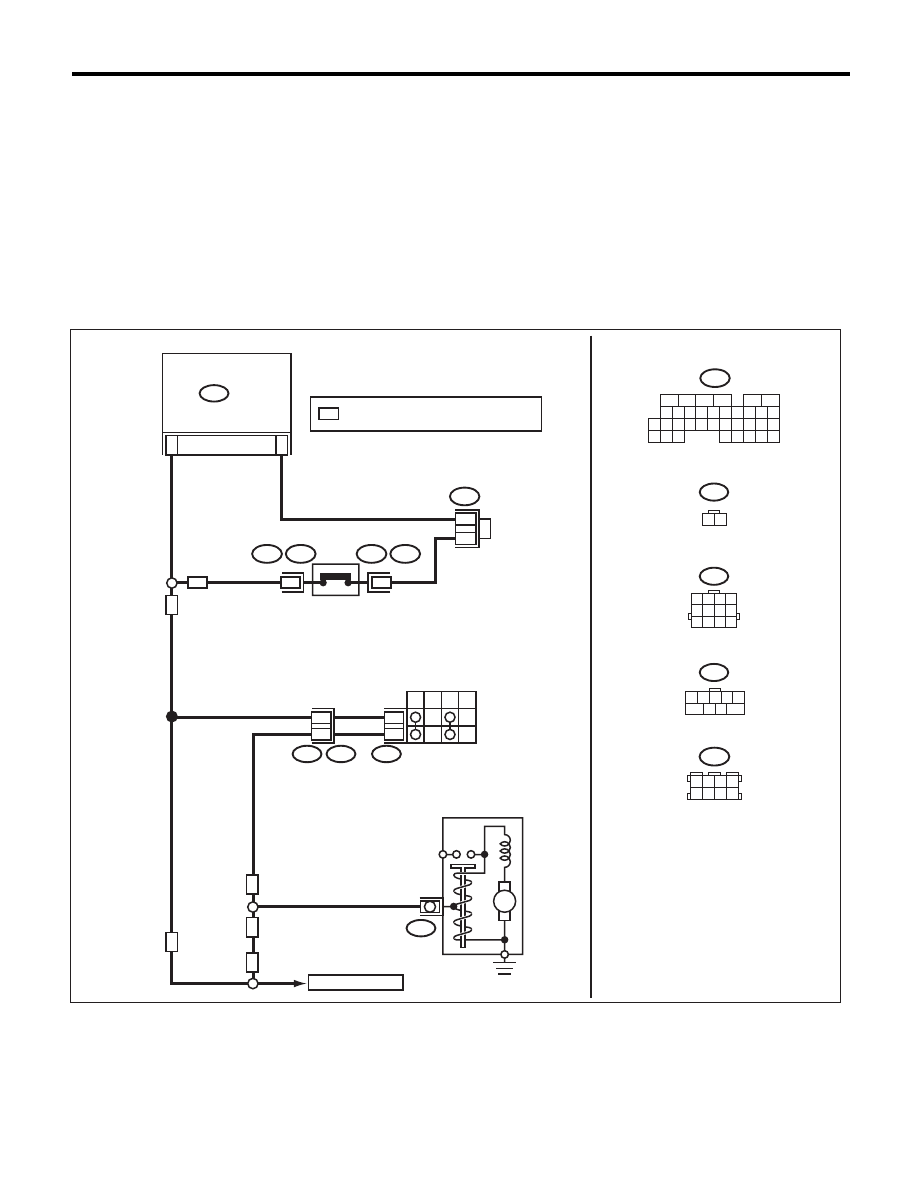
WIRING DIAGRAM:
EN-06642
B12
T3
B14
T7
INHIBITOR
SWITCH
NEUTRAL
POSITION
SWITCH
STARTER MOTOR
(MAGNET)
P
R
N
D
6
9
12
11
B136
ECM
31
6
B12
B25
T7
1 2 3 4
5 6 7 8
9 10 11 12
B136
1
B25
T2
T2
B25
2
MT
AT
AT
AT
MT
MT
M
2
1
C:
C:
B122
*
*
: TERMINAL No. OPTIONAL ARRANGEMENT
*
16
10 11 12 13 14 15
25
24
30
9
8
7
17 18 19 20
28
21 22 23
29
32
31
1
2
3
4
5
6
27
26
33 34 35
B122
3 4
5 6
1 2
7 8
TO STARTER RELAY
1 2 3 4 5
7
6
9
8