Subaru Legacy IV (2008 year). Manual - part 158
 

  Index      Subaru     Subaru Legacy IV - service repair manual 2008 year


Search            


Content   ..  156  157  158  159   ..


Subaru Legacy IV (2008 year). Manual - part 158


EN(H4SO)(diag)-235

Diagnostic Procedure with Diagnostic Trouble Code (DTC)

ENGINE (DIAGNOSTICS)

CE:DTC P0851 NEUTRAL SWITCH INPUT CIRCUIT LOW (MT MODEL)

DTC DETECTING CONDITION:
• Two consecutive driving cycles with fault
• GENERAL DESCRIPTION <Ref. to GD(H4SO)-153, DTC P0851 NEUTRAL SWITCH INPUT CIRCUIT
LOW (MT MODEL), Diagnostic Trouble Code (DTC) Detecting Criteria.>
TROUBLE SYMPTOM:
Improper idling

CAUTION:
After repair or replacement of faulty parts, perform Clear Memory Mode <Ref. to EN(H4SO)(diag)-50,
OPERATION, Clear Memory Mode.>, and Inspection Mode <Ref. to EN(H4SO)(diag)-41, PROCEDURE,
Inspection Mode.>.
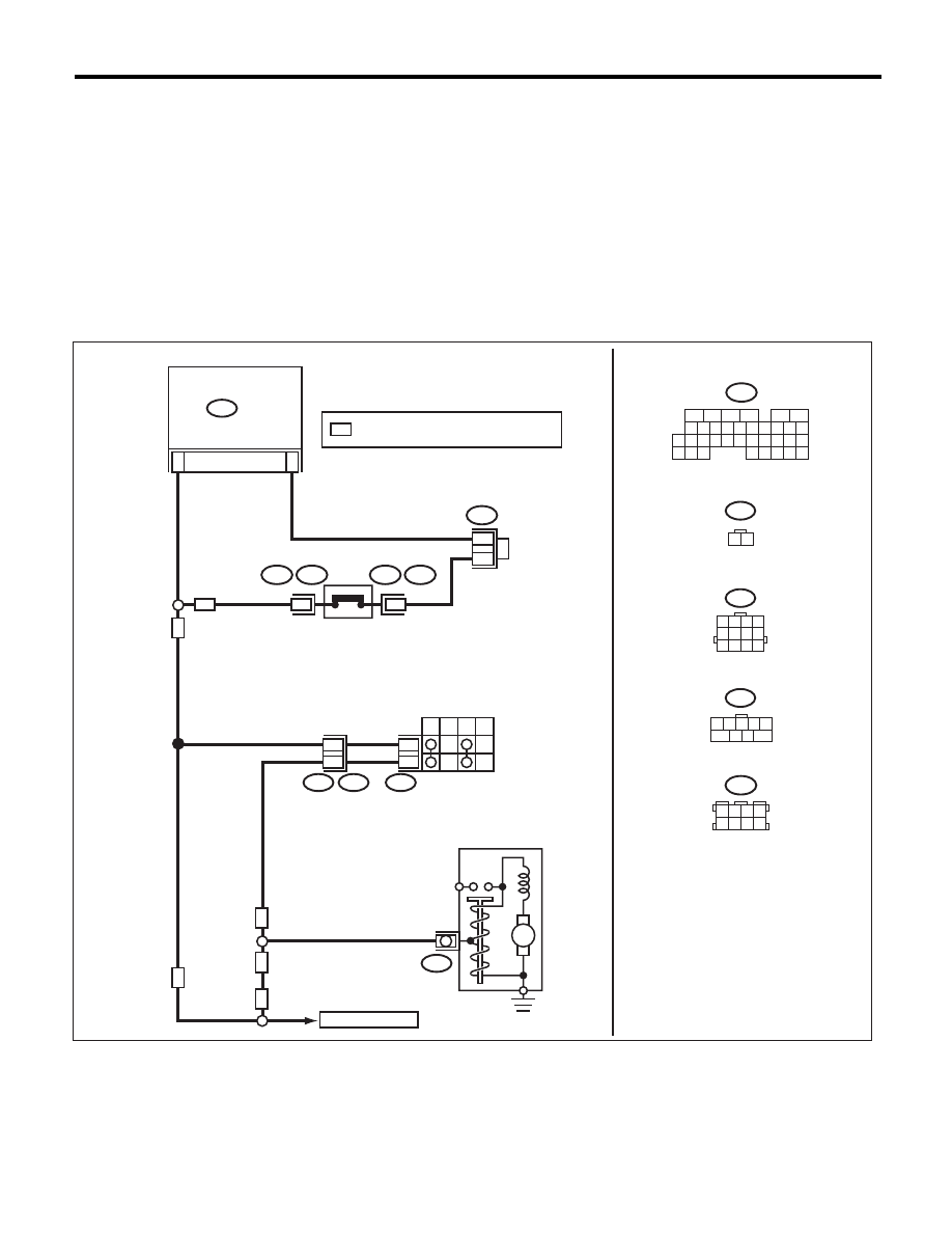
WIRING DIAGRAM:

EN-06642

B12

T3

B14

T7

INHIBITOR

SWITCH

NEUTRAL
POSITION

SWITCH

STARTER MOTOR

(MAGNET)

P

R

N

D

6

9

12

11

B136

ECM

31

6

B12

B25

T7

1 2 3 4
5 6 7 8
9 10 11 12

B136

1

B25

T2

T2

B25

2

MT

AT

AT

AT

MT

MT

M

2

1

C:

C:

B122

*

*

: TERMINAL No. OPTIONAL ARRANGEMENT

*

16

10 11 12 13 14 15

25

24

30

9

8

7

17 18 19 20
28

21 22 23

29

32

31

1

2

3

4

5

6

27

26

33 34 35

B122

3 4

5 6

1 2

7 8

TO STARTER RELAY

1 2 3 4 5

7

6

9

8

EN(H4SO)(diag)-236

Diagnostic Procedure with Diagnostic Trouble Code (DTC)

ENGINE (DIAGNOSTICS)

Step

Check

Yes

No

1

CHECK INPUT SIGNAL OF ECM.
1) Turn the ignition switch to ON.
2) Place the shift lever in a position other than 
neutral.
3) Measure the voltage between ECM and 
chassis ground.

Connector & terminal

(B136) No. 31 (+) — Chassis ground (–):

Is the voltage 10 V or more?

Repair the poor 
contact of ECM 
connector.

Go to step 2.

2

CHECK HARNESS BETWEEN ECM AND 
NEUTRAL POSITION SWITCH CONNEC-
TOR.
1) Turn the ignition switch to OFF.
2) Disconnect the connectors from ECM and 
transmission harness connector (T2).
3) Measure the resistance between ECM and 
chassis ground.

Connector & terminal

(B136) No. 31 — Chassis ground:

Is the resistance 1 M

: or 

more?

Repair the short 
circuit of transmis-
sion harness or 
replace neutral 
position switch. 
<Ref. to 5MT-35, 
Switches and Har-
ness.>

Repair the ground 
short circuit of har-
ness between 
ECM and transmis-
sion harness con-
nector.

EN(H4SO)(diag)-237

Diagnostic Procedure with Diagnostic Trouble Code (DTC)

ENGINE (DIAGNOSTICS)

CF:DTC P0852 PARK/NEUTRAL SWITCH INPUT CIRCUIT HIGH (AT MODEL)

DTC DETECTING CONDITION:
• Two consecutive driving cycles with fault
• GENERAL DESCRIPTION <Ref. to GD(H4SO)-154, DTC P0852 PARK/NEUTRAL SWITCH INPUT CIR-
CUIT HIGH (AT MODEL), Diagnostic Trouble Code (DTC) Detecting Criteria.>
TROUBLE SYMPTOM:
Improper idling

CAUTION:
After repair or replacement of faulty parts, perform Clear Memory Mode <Ref. to EN(H4SO)(diag)-50,
OPERATION, Clear Memory Mode.>, and Inspection Mode <Ref. to EN(H4SO)(diag)-41, PROCEDURE,
Inspection Mode.>.
WIRING DIAGRAM:

EN-06642

B12

T3

B14

T7

INHIBITOR

SWITCH

NEUTRAL
POSITION

SWITCH

STARTER MOTOR

(MAGNET)

P

R

N

D

6

9

12

11

B136

ECM

31

6

B12

B25

T7

1 2 3 4
5 6 7 8
9 10 11 12

B136

1

B25

T2

T2

B25

2

MT

AT

AT

AT

MT

MT

M

2

1

C:

C:

B122

*

*

: TERMINAL No. OPTIONAL ARRANGEMENT

*

16

10 11 12 13 14 15

25

24

30

9

8

7

17 18 19 20
28

21 22 23

29

32

31

1

2

3

4

5

6

27

26

33 34 35

B122

3 4

5 6

1 2

7 8

TO STARTER RELAY

1 2 3 4 5

7

6

9

8

EN(H4SO)(diag)-238

Diagnostic Procedure with Diagnostic Trouble Code (DTC)

ENGINE (DIAGNOSTICS)

Step

Check

Yes

No

1

CHECK SELECT CABLE.

Are there any faults in the select 
cable?

Repair or adjust 
the select cable. 
<Ref. to CS-28, 
Select Cable.>

Go to step 2.

2

CHECK INPUT SIGNAL OF ECM.
1) Turn the ignition switch to ON.
2) Measure the voltage between ECM and 
chassis ground with select lever at “P” range 
and “N” range.

Connector & terminal

(B136) No. 31 (+) — Chassis ground (–):

Is the voltage less than 1 V?

Repair the poor 
contact of ECM 
connector.

Go to step 3.

3

CHECK HARNESS BETWEEN ECM AND IN-
HIBITOR SWITCH CONNECTOR.
1) Turn the ignition switch to OFF.
2) Disconnect the connector from ECM and 
inhibitor switch.
3) Measure the resistance of harness between 
ECM and inhibitor switch connector.

Connector & terminal

(B136) No. 31 — (T7) No. 6:

Is the resistance less than 1 

:? Go to step 4.

Repair the harness 
and connector.

NOTE:
In this case, repair
the following item:
• Open circuit in
harness between
ECM and inhibitor
switch connector
• Poor contact of
coupling connector

4

CHECK INHIBITOR SWITCH GROUND LINE.
Measure the resistance of harness between 
inhibitor switch connector and engine ground.

Connector & terminal

(T7) No. 9 — Engine ground:

Is the resistance less than 5 

:? Replace the inhibi-

tor switch. <Ref. to 
4AT-46, Inhibitor 
Switch.>

Repair the harness 
and connector.

NOTE:
In this case, repair
the following item:
• Open circuit in
harness between
inhibitor switch
connector and
starter motor
ground line
• Poor contact of
coupling connector
• Poor contact in
starter motor con-
nector
• Poor contact in
starter motor
ground
• Starter motor


Content   ..  156  157  158  159   ..