Content .. 1238 1239 1240 1241 ..
Subaru Legacy IV (2008 year). Manual - part 1240
WI-212
Engine Wiring Harness and Transmission Cord
WIRING SYSTEM
57.Engine Wiring Harness and Transmission Cord
A: LOCATION
1. 2.5 L NON-TURBO MODEL
MT MODEL
AT MODEL
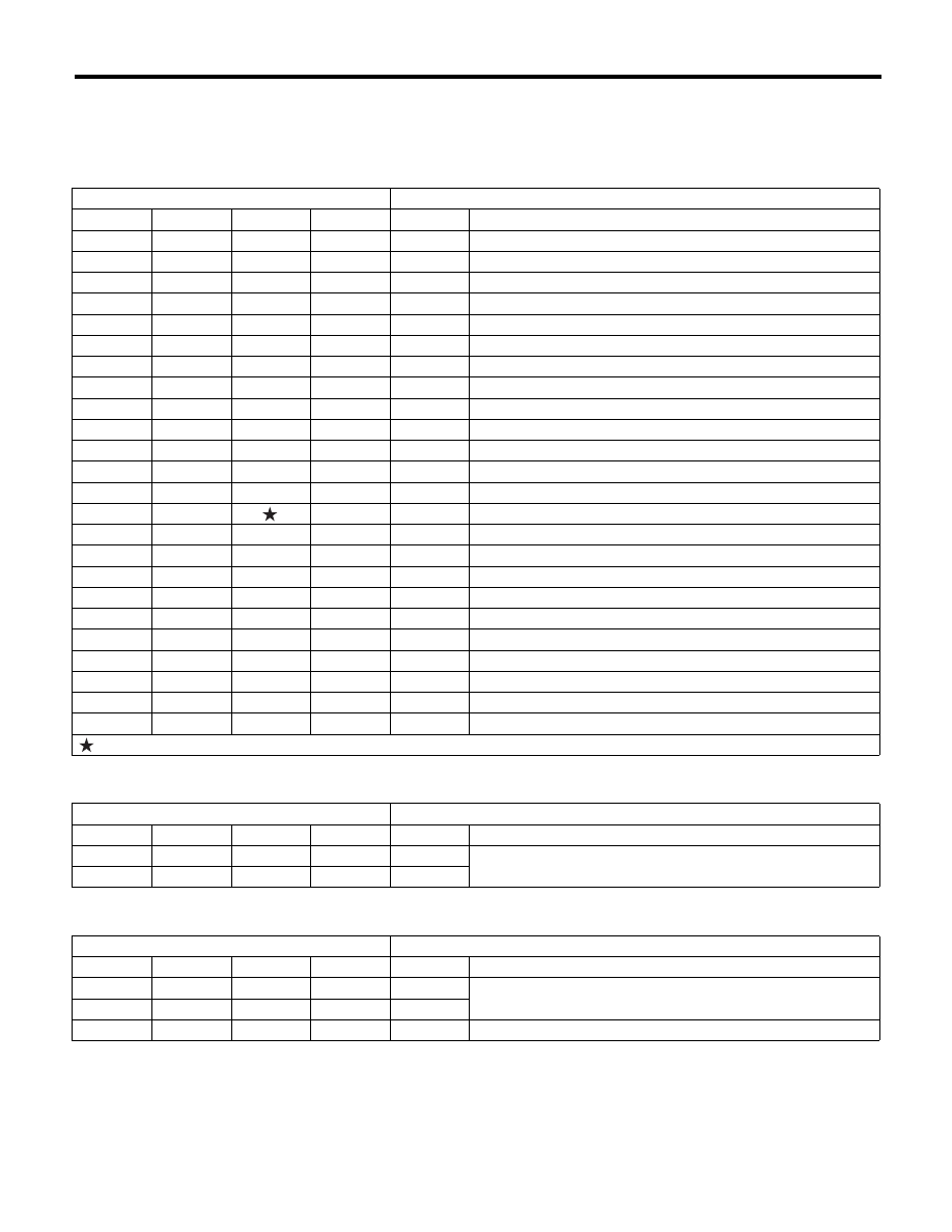
Connector
Connecting to
No.
Pole
Color
Area
No.
Description
E2
54
Black
A-3
B21
Bulkhead wiring harness
E4
2
Black
A-2
Purge control solenoid valve
E5
2
Dark gray
B-1
Fuel injector No. 1
E6
2
Dark gray
A-2
Fuel injector No. 3
E8
2
Black
B-2
Engine coolant temperature sensor
E10
2
Light gray
B-3
Crankshaft position sensor
E11
1
—
B-2
Oil pressure switch
E12
4
Dark gray
A-2
Ignition coil and ignitor ASSY
E14
2
Gray
B-4
Knock
sensor
E15
2
Gray
B-4
Camshaft position sensor
E16
2
Dark gray
B-5
Fuel injector No. 2
E17
2
Dark gray
B-5
Fuel injector No. 4
E18
6
Dark gray
A-4
EGR valve
E19
1
B-2
Power steering oil pressure switch
E21
3
Black
A-4
Manifold absolute pressure sensor
E22
6
Dark gray
A-1
Front oxygen (A/F) sensor
E23
4
Dark gray
A-1
Rear Oxygen Sensor
E57
6
Black
A-3
Electronic throttle control
E61
2
Dark gray
A-3
PCV diagnosis connector
E67
2
Blue
A-2
Oil switching solenoid valve RH
E68
2
Blue
B-4
Oil switching solenoid valve LH
E71
1
Gray
A-3
Variable valve lift diagnosis oil pressure switch RH
E72
1
Gray
B-4
Variable valve lift diagnosis oil pressure switch LH
E75
2
Black
A-3
Oil
temperature
sensor
: White or natural color
Connector
Connecting to
No.
Pole
Color
Area
No.
Description
T1
2
Gray
C-2
B24
Bulkhead wiring harness
T2
2
Brown
D-4
B25
Connector
Connecting to
No.
Pole
Color
Area
No.
Description
T3
12
Black
D-4
B12
Bulkhead wiring harness
T4
20
Gray
D-4
B11
T7
9
Black
D-5
Inhibitor
switch