Content .. 1182 1183 1184 1185 ..
Subaru Legacy IV (2008 year). Manual - part 1184
LAN(diag)-70
Diagnostic Procedure with Diagnostic Trouble Code (DTC)
LAN SYSTEM (DIAGNOSTICS)
Q: DTC U1301 CAN-LS COUNTER ABNORMAL
DTC DETECTING CONDITION:
Find the unit in which trouble occurs and open or short CAN line, and repair and replace them.
(Free running counter error may be detected at the same time from the unit in which the malfunction occurs.)
TROUBLE SYMPTOM:
“Er LC” is displayed in odo/trip meter. (Except for meter with MID)
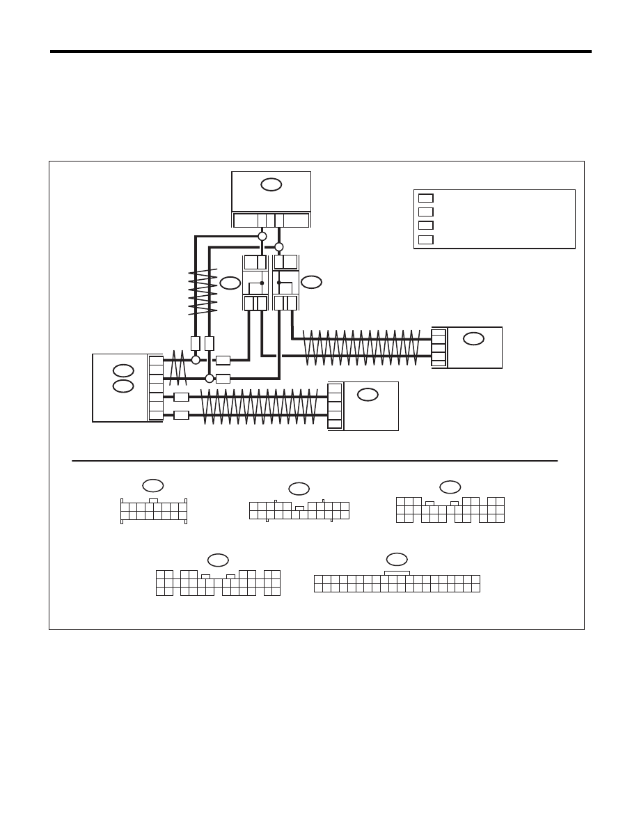
WIRING DIAGRAM:
i106
i10
B282
21
22
14
6
i119
A27
A26
B26
B25
i84
B280
10
9
B:
A:
B:
i107
*
1
*
1
*
1
*
1
*
1
*
1
i10
LAN00383
CAN
JOINT
CONNECTOR
ON
WN
WN
ON
TWISTED PAIR LINE
TWISTED PAIR LINE
COMBINATION METER
BODY
INTEGRATED
UNIT
i119
1 2 3 4 5 6 7 8
9 10 11 12 13 14 15 16
1 2 3 4 5
6 7 8 9 10
11 12
19 20 21
13 14 15 16 17 18
22
5
4
6 7
8
2
1
9
3
10
22
23
11 12 13 14 15
24 25
26 27
16 17 18
28 29
19 20
21
30
B280
A:
i84
1 2
3 4
5 6
7 8
9 10 11 12
14 15 16 17 18 19 20 21 22 23
24 25
26 27 28 29
30 31 32 33
34 35
13
B282
1 2 3 4 5 6 7 8 9 10 11 12 13 14 15 16 17 18 19 20
21 22 23 24 25 26 27 28 29 30 31 32 33 34 35 36 37 38 39 40
*
1
ON
WN
WA
WA
WA
AUTO A/C
CONTROL
MODULE
CENTER
DISPLAY
: TERMINAL No. OPTIONAL ARRANGEMENT
: WITH NAVIGATION
: WITHOUT NAVIGATION
: WITH AUTO A/C