Content .. 1166 1167 1168 1169 ..
Subaru Legacy IV (2008 year). Manual - part 1168
LAN(diag)-6
General Description
LAN SYSTEM (DIAGNOSTICS)
C: PREPARATION TOOL
1. SPECIAL TOOL
2. GENERAL TOOL
ILLUSTRATION
TOOL NUMBER
DESCRIPTION
REMARKS
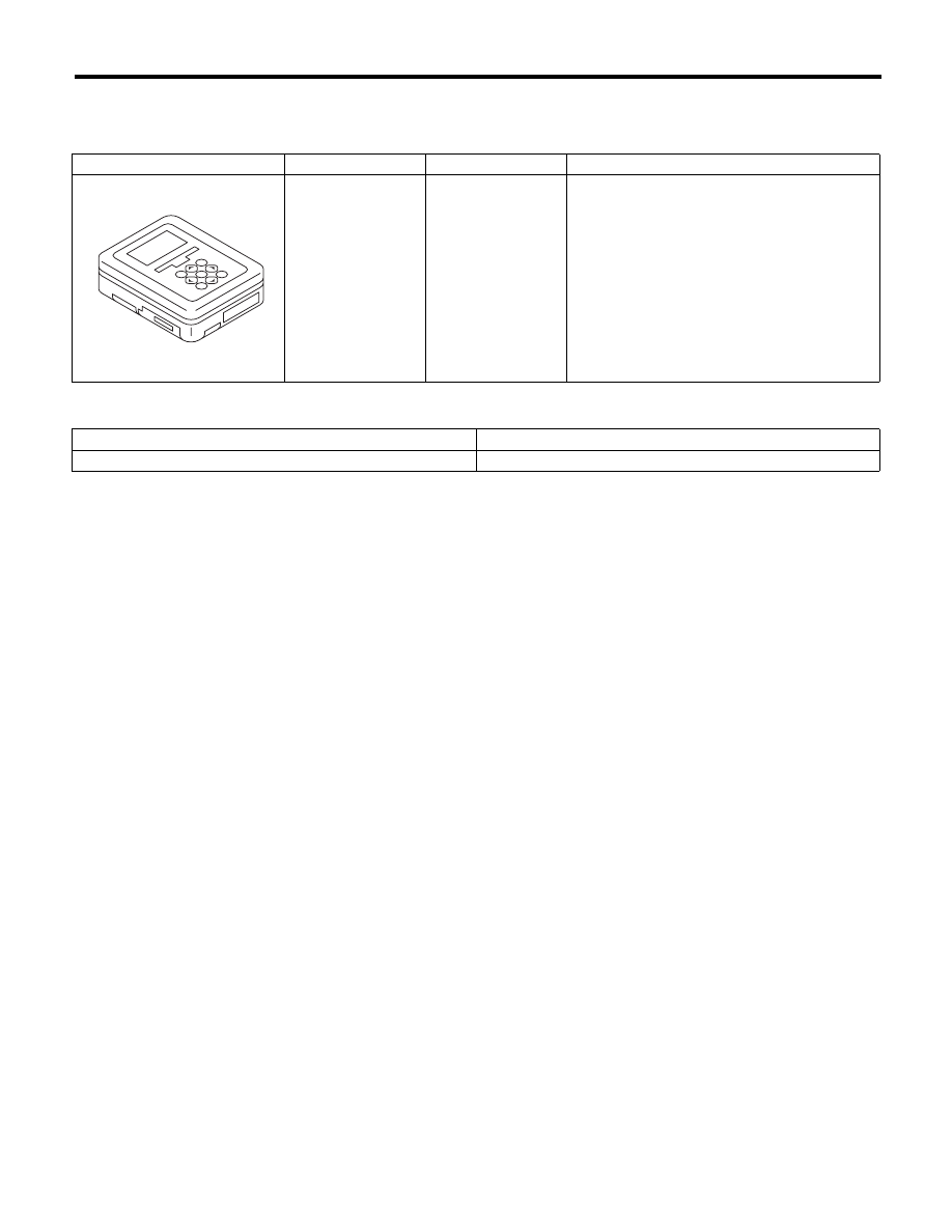
1B022XU0
SUBARU SELECT
MONITOR III KIT
Used for troubleshooting the electrical system.
TOOL NAME
REMARKS
Circuit tester
Used for measuring resistance, voltage and current.
ST1B022XU0