Content .. 1108 1109 1110 1111 ..
Subaru Legacy IV (2008 year). Manual - part 1110
SL-13
Keyless Entry System
SECURITY AND LOCKS
3. Keyless Entry System
A: WIRING DIAGRAM
1. KEYLESS ENTRY
For wiring diagrams related to the keyless entry system, refer to “Keyless Entry System” in Section WI. <Ref.
to WI-190, WIRING DIAGRAM, Keyless Entry System.>
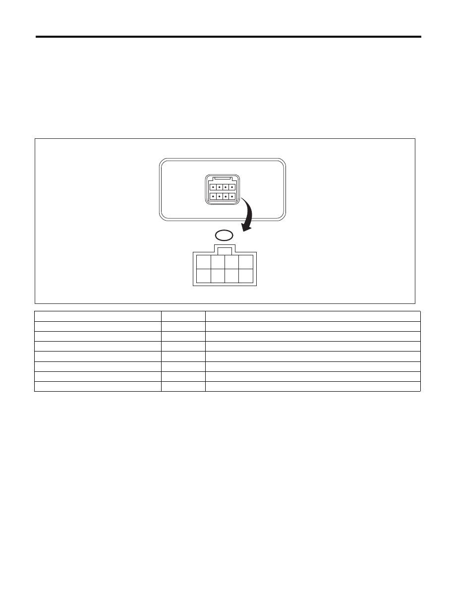
B: ELECTRICAL SPECIFICATION
1. KEYLESS ENTRY CONTROL MODULE
2. BODY INTEGRATED UNIT
Refer to the Control Module I/O Signal of the LAN SYSTEM (DIAGNOSTICS). <Ref. to LAN(diag)-9, ELEC-
TRICAL SPECIFICATION, Control Module I/O Signal.>
Remarks
Terminal No.
Measuring condition
-
1
-
-
2
-
Body integrated unit
3 (OUTPUT)
Battery voltage cannot be measured because of digital signal.
Power supply (Backup)
4
Battery voltage is constantly present.
-
5
-
-
6
-
Ground
7
0 V is constantly present.
SL-00946
4 3 2 1
8 7 6 5
i96
TO