Subaru Legacy IV (2008 year). Manual - part 1101


  Index      Subaru     Subaru Legacy IV - service repair manual 2008 year


Search            


Content   ..  1099  1100  1101  1102   ..


Subaru Legacy IV (2008 year). Manual - part 1101


SE-16

Front Seat

SEATS

D: ASSEMBLY

CAUTION:
When the backrest cover is not installed se-
curely, the side airbag module may not be de-
ployed properly, therefore keep strictly to the
following procedure.
• Be careful not to stain or damage the back-
rest cover during assembly.
• The backrest cover of the side airbag module
are to be tightened and fixed together with the
attachment nuts for the side airbag module as-
sembly.
• Always use new hog rings.
• Secure the hog ring using hog ring pliers.
• Install the hog rings to the specified points
securely and make sure that no wrinkle or twist-
ing on backrest cover.

1. DRIVER’S SEAT

NOTE:
• When installing the inner seat belt assembly, fol-
low the procedures described in the seat belt sec-
tion. <Ref. to SB-19, INNER SEAT BELT
ASSEMBLY, INSTALLATION, Front Seat Belt.>
• Install the backrest assembly and seat cushion
assembly in the following procedure.
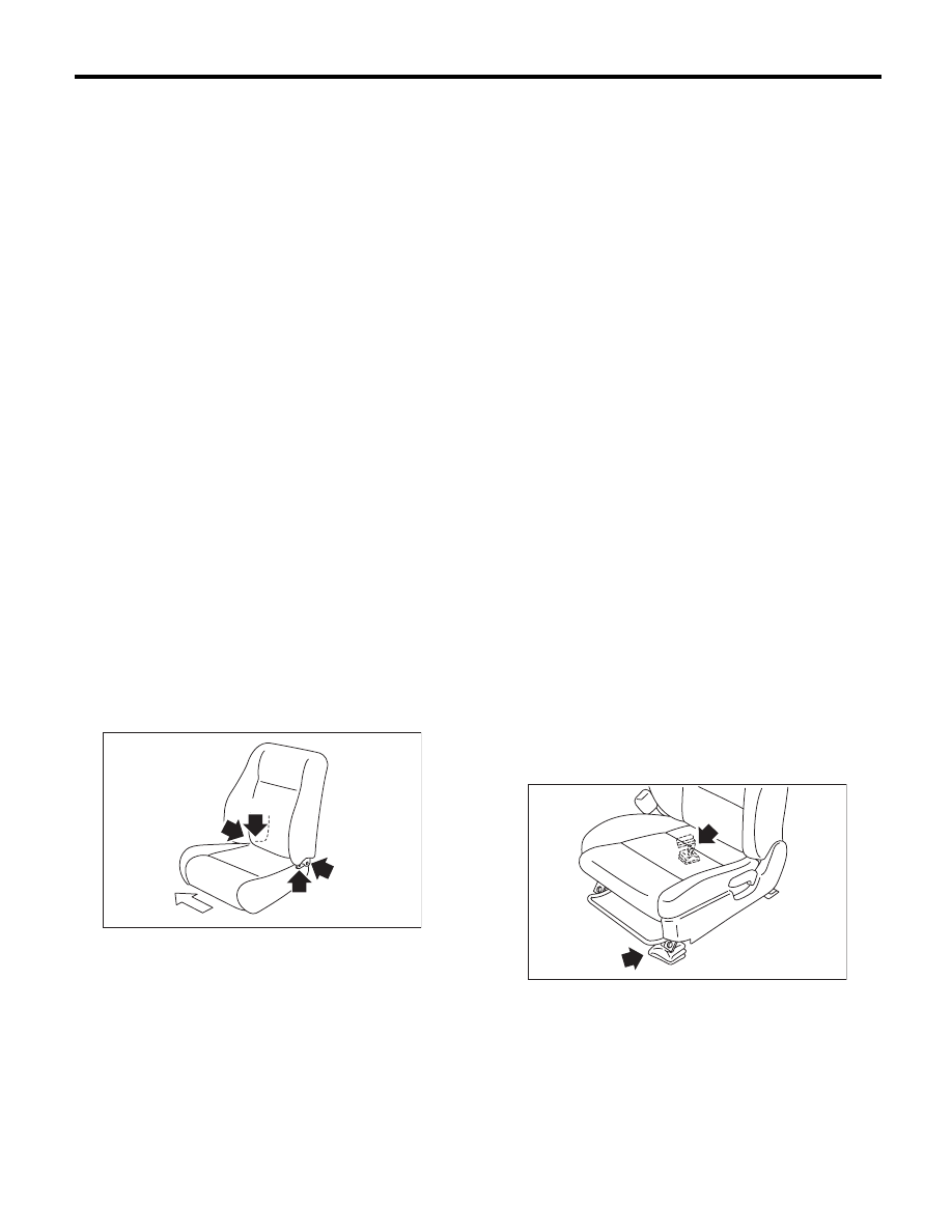
1) Temporarily tighten the four reclining hinge
bolts.
2) Place the backrest in the most upright position.
3) Tighten the reclining hinge bolts in the order of
(1) through (4), in two or three steps by gradually in-
creasing the torque until they reach the specified
torque.

4) Assemble in the reverse order of disassembly.

2. PASSENGER’S SEAT

CAUTION:
Make sure to adhere to the following rules when
assembling the passenger seat. Improper work
procedures can cause the passenger detection
system to not operate properly.
• If the seat cushion cover is removed or re-
placed, make sure to perform occupant detec-
tion system adjustment after installing the seat.
<Ref. to OD(diag)-15, SYSTEM CALIBRATION
(REZEROING), OPERATION, Subaru Select
Monitor.>
Failure to do so may prevent the passenger’s
airbag from operating properly.
• The passenger detection system (passenger
seat only) control unit, passenger detection
sensor, seat cushion pad and seat cushion
frame are considered as a single seat cushion
pad and frame assembly. Never remove the
passenger detection control unit or the pres-
sure sensor from the seat cushion frame.
• If the seat cushion cover is removed, make
sure to replace the hang wire on the seat cush-
ion side with a new wire.
• Make sure to install the hog rings/clips to the
specified locations. Do not reuse hog rings.
Assemble in the reverse order of disassembly.
1) Assemble the seat cushion in the reverse order
of disassembly.
2) Assemble the backrest in the reverse order of
disassembly.
3) When installing the backrest assembly to the
seat cushion assembly, fill the gap in the front side
of slide rail LH and in the rear side of slide rail RH
with cloth etc. in order to stabilize the seat cushion
assembly.

(A) Vehicle inside

(B) Vehicle outside

(A)

(B)

(2)

(4)

(3)

(1)

SE-00514

SE-00537

SE-17

Front Seat

SEATS

4) Temporarily tighten the reclining hinge bolts in
the order of (1) through (4) to an extent that the seat
backrest assembly is not held securely.

5) Use the reclining lever to place the backrest in
the most upright position, and check the first lock
position of recliner.
6) Hold the seat cushion assembly securely, and
tighten the reclining hinge bolts in the order de-
scribed above until they reach the specified torque.

CAUTION:
Do not touch the backrest assembly when tight-
ening the reclining hinge bolts.
7) Assemble each harness, inner belt assembly
and each cover in the reverse order of removal.

Tightening torque:

Refer to “COMPONENT” of “General Descrip-
tion”. <Ref. to SE-2, COMPONENT, General 
Description.>

E: INSPECTION

Check that no tear or fray on the backrest cover
and seat cushion cover.

NOTE:
If the door side of the backrest cover is torn or
frayed, the side airbag may not be deployed prop-
erly. In this case, replace the backrest cover.

(A) Vehicle inside

(B) Vehicle outside

(A)

(B)

(2)

(4)

(3)

(1)

SE-00538

SE-18

Rear Seat

SEATS

3. Rear Seat

A: REMOVAL

CAUTION:
• Airbag system satellite safing sensor is lo-
cated in the lower of the rear seat cushion cen-
ter. Read the cautions given in AB section
before removing the rear seat. <Ref. to AB-4,
CAUTION, General Description.>
• The airbag system is fitted with a backup
power source. After disconnecting the battery
ground cable, the airbag may deploy if you do
not wait for 20 seconds before starting the ser-
vice of airbag system.

1. SEDAN MODEL

1) Remove the two hooks while lifting up the rear
seat cushion.

2) Remove the hook (A) by pushing it back while
lifting the front side of the seat cushion, and remove
the seat cushion.

3) Tilt the backrest forward, remove the plastic fas-
tener at the rear mat.

4) Remove the hinge assembly center bolts.

5) Push the entire seat to the direction of arrow and
remove backrest assembly LH from the hinge as-
sembly.

NOTE:
The backrest cannot be detached while the cutout
on hinge assembly side and the pin on the backrest
side are not aligned.
6) Similarly, remove the backrest assembly RH by
performing the above step 5).
7) Remove the backrest shoulder. (Right and left)

(1) Remove the bolt.
(2) Moving the lower side of backrest shoulder
to the direction of arrow, and remove it from the
stud bolt.
(3) Lift to remove the backrest shoulder.

SE-00343

SE-00345

(A)

SE-00759

SE-00694

SE-00760

(1)

(3)

(2)

SE-19

Rear Seat

SEATS

8) Remove the two bolts at front side of the hinge
assembly center.

2. WAGON MODEL

1) Remove the two hooks while lifting up the rear
seat cushion.

2) Remove the hook (A) by pushing it back while
lifting the front side of the seat cushion, and remove
the seat cushion.

3) Remove the headrest, and then tilt the backrest
forward.
4) Remove the luggage floor box. <Ref. to EI-73,
REMOVAL, Luggage Floor Box.>

5) Peel the plastic fastener of rear face mat and re-
move the hinge assembly center bolts.

6) Remove the backrest assembly LH from hinge
assembly LH.

NOTE:
The backrest cannot be detached while the hinge
assembly side and the backrest pin are not aligned.
7) Similarly, remove the backrest assembly RH by
performing the above step 8).
8) Remove the hinge assembly center bolts.

9) Remove the lower anchor bolt (A) of the outer
seat belt and backrest shoulder bolt (B).

SE-00698

SE-00343

SE-00397

(A)

SE-00153

SE-00348

SE-00733

SE-00699

(B)

(A)


Content   ..  1099  1100  1101  1102   ..