Content .. 1090 1091 1092 1093 ..
Subaru Legacy IV (2008 year). Manual - part 1092
IDI-9
Combination Meter System
INSTRUMENTATION/DRIVER INFO
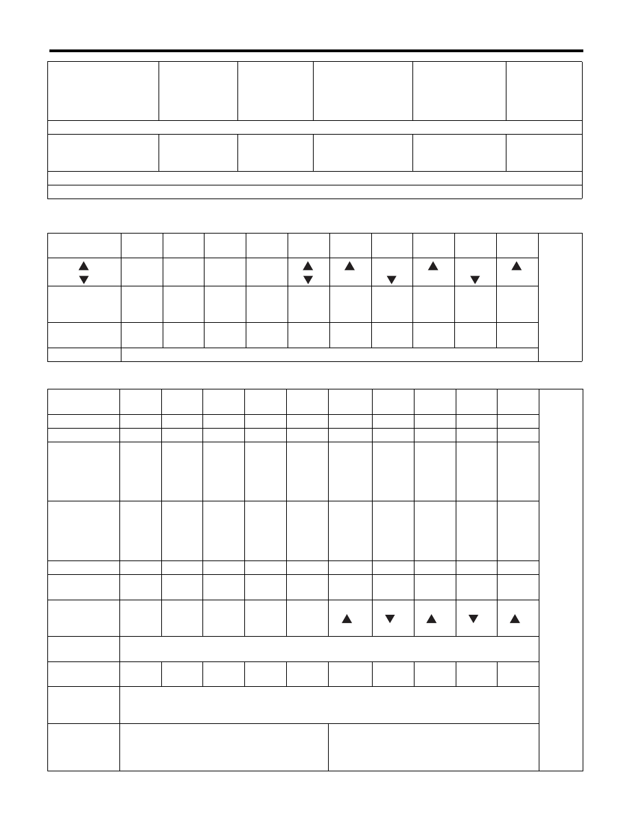
• Illuminating order table
Display Contents 1
Display Contents 2
Step 4-2. Press the trip knob: Check the beeping of SPORT shift buzzer (For AT model only, while for MT model, go to the next)
All meter indicator nee-
dle returns to lowest
position.
Light OFF
Shift display
blinks with
buzzer.
STEP 4 SS BUZZER
is displayed.
Light at the highest
brightness.
SPORT shift
buzzer beeps.
Step 5. Press the trip knob: Complete the self-diagnosis 1 cycle
All meter indicator needle returns to lowest position, and go back to step 1 after completion.
Illuminating
order
1
2
3
4
5
6
7
8
9
10
Go back
to 1 and
repeat
AT select lever
position indicator
P
R
N
D
All
lights
ON
1
2
3
4
5
Display time
(seconds)
1
0.5
0.5
0.5
1
0.5
0.5
0.5
0.5
0.5
Back-up light
White light ON
Illuminating
order
1
2
3
4
5
6
7
8
9
10
Go back
to 1 and
repeat.
Speedometer
0
0
40
60
80
100
80
60
40
0
Tachometer
0
0
1000
2000
3000
4000
3000
2000
1000
0
Fuel gauge
Lowest
position
EMPTY
Warn-
ing light
illumi-
nation
position
1/2
FULL
Highest
position
FULL
1/2
Warn-
ing light
illumi-
nation
position
EMPTY
Engine coolant
temperature
gauge
Lowest
position
C
at the
first
scale
1/2
at the
third
scale
over the
fourth
scale
(approx.
120°C)
at the
third
scale
1/2
at the
first
scale
C
ECO gauge
–Max
0
+Max
0
–Max
0
+Max
0
–Max
0
Low fuel
warning light
Light
ON
Light
ON
Light
ON
Light
OFF
Light
OFF
Light
OFF
Light
OFF
Light
OFF
Light
ON
Light
ON
AT select lever
position
indicator
P
R
N
D
All
lights
ON
1
2
3
4
5
Multi-informa-
tion display
STEP 2 is displayed.
Display time
(seconds)
2.5
2.5
2.5
2.5
2.5
2.5
2.5
2.5
2.5
2.5
Back-up light
(SS of AT
model)
White light ON
Back-up light
(Multi informa-
tion display
LCD)
White light ON
Yellow light ON
Speedometer, tachome-
ter, fuel gauge, engine
coolant temperature
gauge, ECO gauge
Microcomputer
running type
warning light,
indicator light
AT select lever
position indica-
tor light
Multi-information dis-
play
Illumination
(indicator needle,
plate, ring, LCD)
Buzzer (SPORT
shift buzzer,
VDC buzzer,
vehicle speed
warning buzzer)