Content .. 1061 1062 1063 1064 ..
Subaru Legacy IV (2008 year). Manual - part 1063
ET-9
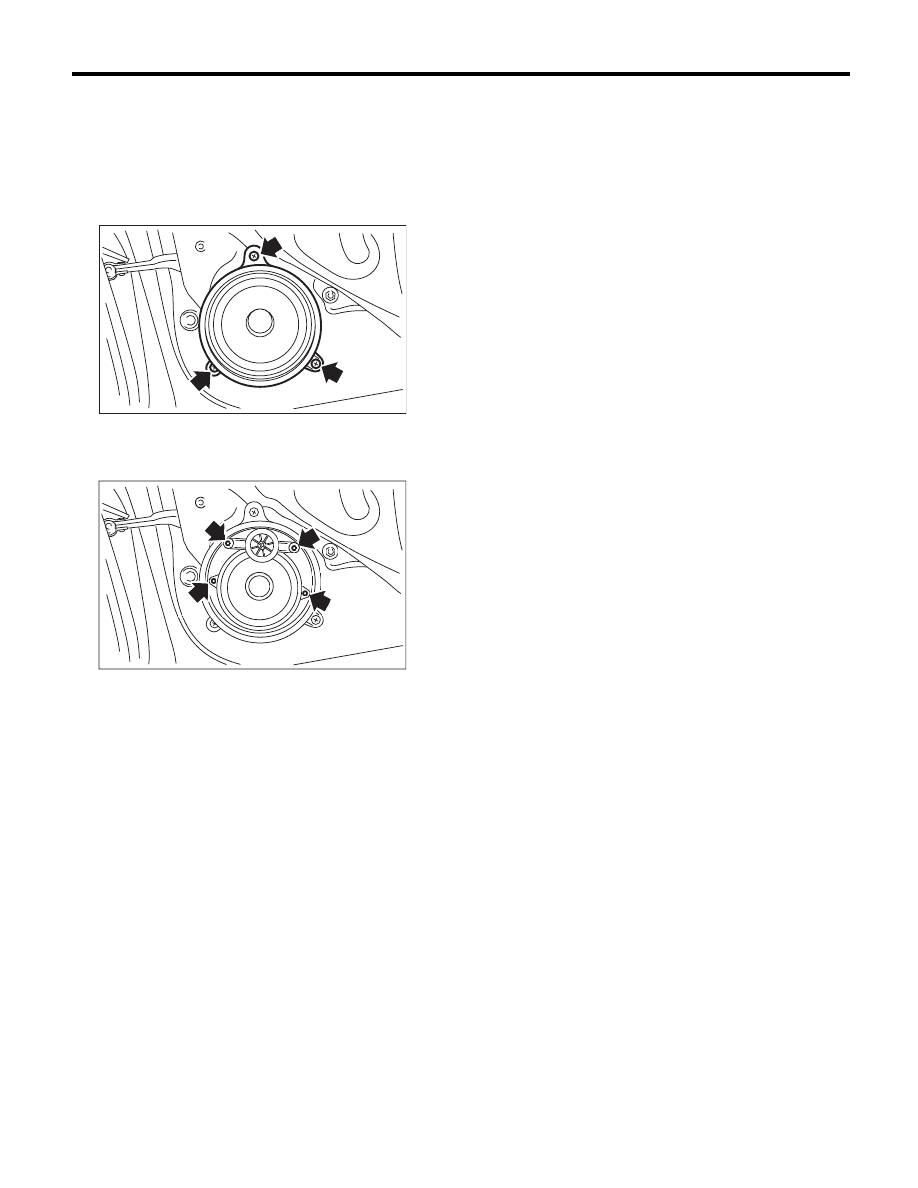
Rear Speaker
ENTERTAINMENT
6. Rear Speaker
A: REMOVAL
1) Disconnect the ground cable from the battery.
2) Remove the rear door trim. <Ref. to EI-49, RE-
MOVAL, Door Trim.>
3) Remove the rear speaker mounting screws.
CAUTION:
Do not disassemble the rear speaker of premi-
um audio system.
4) Disconnect the harness connector and remove
the rear speaker.
B: INSTALLATION
Install in the reverse order of removal.
ET-00084
ET-00323
G
G
G
G
G
G
G
G
G
G
G
G
G
G
G
G
G
G
G
G
G
G
NG
G
N
N
N
N
N
N
N
N
N
N
N
N
N
N
N
NG
N
N
N
NG
G
G
N
NG
NG
N
N
G
G
NG
NG
G
NG
G
G
G
G
G
G
N
N
G
G
N
N
G
G
N
NG
G
G
G
G
G