Subaru Legacy IV (2008 year). Manual - part 98


  Index      Subaru     Subaru Legacy IV - service repair manual 2008 year


Search            


Content   ..  96  97  98  99   ..


Subaru Legacy IV (2008 year). Manual - part 98


SC(H4SO)-16

Generator

STARTING/CHARGING SYSTEMS

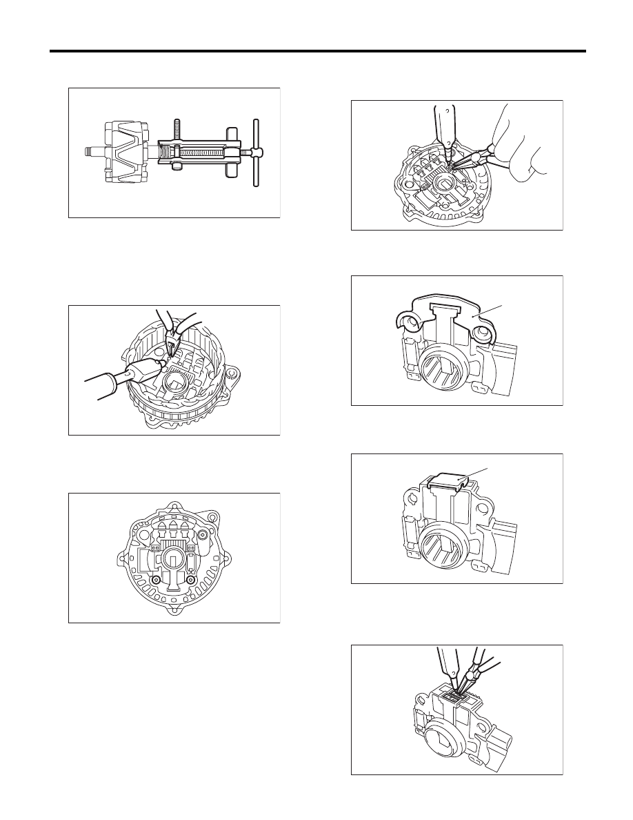
6) Using the bearing puller, remove the bearings
from the rotor.

7) Disconnect the connection between the rectifier
and stator coil, then remove the stator coil.

CAUTION:
The rectifier is easily damaged by heat. Do not
allow a 180 — 270 W soldering iron to contact
the terminals for 5 seconds or more at a time.

8) Use the following procedures to remove the IC
regulator.

(1) Remove the screws which secure the IC
regulator to the rear cover.

(2) Disconnect the connection between the IC
regulator and rectifier, then remove the IC reg-
ulator.

9) Use the following procedures to remove the
brush.

(1) Remove the cover A.

(2) Remove the cover B.

(3) Disconnect the connection and remove the
brush.

SC-00046

SC-00083

SC-00084

(A) Cover A

(A) Cover B

SC-00085

SC-00086

(A)

SC-00087

(A)

SC-00088

SC(H4SO)-17

Generator

STARTING/CHARGING SYSTEMS

10) Remove the rectifier as follows.

(1) Remove the bolts which secure the rectifier.

(2) Remove the cover on terminal B.

(3) Remove the nuts of terminal B, then remove
the rectifier.

D: ASSEMBLY

Assemble in the reverse order of disassembly.
1) Pull-out of the brush
Before assembling, press the brush down into the
brush holder, then fix the brush in that position by
inserting a [1 mm (0.04 in) dia., 40 — 50 mm (1.6 —
2.0 in) long] wire through the hole as shown in the
figure.

CAUTION:
After re-assembling, remove the wire.

2) Install the ball bearings.

(1) Set the ball bearings in the front cover, then
securely install an appropriate tool (such as a
socket wrench of proper size) to the bearing
outer race.
(2) Using a press to press the ball bearings into
the specified location.
(3) Install the bearing retainer.

3) Using a press to install the bearings (rear side)
to the rotor shaft.
4) Heat the bearing box in rear cover [50 to 60°C
(122 to 140°F)], and then press the rear bearing
into rear cover.

CAUTION:
Do not apply grease to the rear bearings. If
there is any oil on the bearing box, remove it
completely.
5) After re-assembling, manually turn the pulley to
check that the rotor rotates smoothly.

SC-00089

SC-00090

SC-00091

(A) Wire

SC-00092

(A)

SC(H4SO)-18

Generator

STARTING/CHARGING SYSTEMS

E: INSPECTION

1. DIODE

CAUTION:
There is the possibility of damaging the diodes
if a mega-tester (used to measure high voltag-
es) or a similar measuring instrument is used.
Never use a mega tester or equivalent for this
test.
1) Check the positive diode
Check for continuity between the diode lead and
positive side heat sink. If resistance is 1 

: or less

only in the direction from the diode lead to the heat
sink, the positive diode is OK.

2) Check negative diode
Check for continuity between the negative side
heat sink and diode lead. If resistance is 1 

: or less

only in the direction from the heat sink to the diode
lead, the negative diode is OK.

2. ROTOR

1) Slip ring surface
Inspect the slip rings for contamination or any
roughness on the sliding surface. Repair the slip
ring surface using a lathe or sand paper.
2) Slip ring outer diameter
Measure the slip ring outer diameter. Replace the
rotor assembly if the slip ring is worn.

Slip ring outer diameter:

Standard

22.7 mm (0.894 in)

Limit

22.1 mm (0.870 in)

3) Continuity test
Using a circuit tester, check the resistance between
slip rings.
If the resistance is not within the standard, replace
the rotor assembly.

Specified resistance:

Approximately 1.6 — 1.9 

:

4) Insulation test
Check the continuity between slip ring and rotor
core or shaft. If the resistance is 1 

: or less, re-

place the rotor assembly because the rotor coil is
grounded.

5) Ball bearings (rear side)
Check the rear ball bearing. If there is any noise, or
the rotor does not rotate smoothly, replace the
bearings.

(A) Diode lead

(B) Heat sink (positive side)

(A) Diode lead

(B) Heat sink (negative side)

SC-00042

(B)

(A)

(A)

(B)

SC-00043

SC-00044

SC-00045

SC(H4SO)-19

Generator

STARTING/CHARGING SYSTEMS

3. STATOR

1) Continuity test
Inspect continuity between the stator coil lead wire
terminals. If the resistance is 1 M

: or more, the

lead wire is damaged. Replace the stator assem-
bly.

2) Insulation test
Inspect the continuity between the stator coil stator
core and lead wire terminals. If the resistance is 1 

:

or less, the stator coil is grounded. Replace the sta-
tor assembly.

4. BRUSH

1) Measure the length of each brush. Replace the
brush if wear exceeds service limits. There is a ser-
vice limit mark (A) on each brush.

Brush length:

Service limit (1)

5.0 mm (0.197 in)

Standard (2)

18.5 mm (0.728 in)

2) Check that there is appropriate pressure on the
brush spring.
Using a spring pressure indicator, push the brush
into the brush holder until its tip protrudes 2 mm
(0.08 in). Then measure the pressure of brush
spring. If the pressure is 2.2 N (0.224 kgf, 7.91 oz)
or less, replace the brush spring with a new one.
4.8 — 6.0 N (0.489 — 0.612 kgf, 17.26 — 21.58 oz)
pressure is required on the new spring.

5. BEARING (FRONT SIDE)

Check the front ball bearing. Replace the ball bear-
ings if there is resistance in the rotation, or if there
is any abnormal noise.

(A) Stator

(A)

SC-00047

SC-00048

SC-00162

(A)

(1)

(2)

SC-00093


Content   ..  96  97  98  99   ..