Subaru Legacy IV (2008 year). Manual - part 95
SC(H4SO)-4
General Description
STARTING/CHARGING SYSTEMS
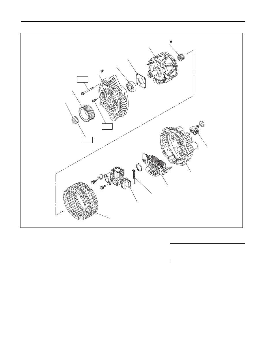
2. GENERATOR
(1)
Pulley nut
(7)
Bearing
(13)
Terminal
(2)
Pulley
(8)
Stator coil
(3)
Front cover
(9)
IC regulator with brush
Tightening torque:N·m (kgf-m, ft-lb)
(4)
Ball bearing
(10)
Brush
T1: 4.7 (0.5, 3.5)
(5)
Bearing retainer
(11)
Rectifier
T2: 108 (11.0, 79.8)
(6)
Rotor
(12)
Rear cover
(1)
(2)
(3)
(4)
(5)
(6)
(7)
(8)
(9)
(10)
(11)
(12)
(13)
T1
T1
T2
SC-02121