Subaru Legacy IV (2008 year). Manual - part 90
LU(H4SO)-17
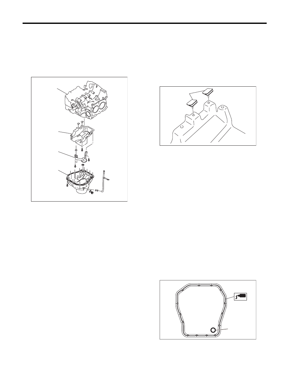
Oil Pan and Strainer
LUBRICATION
18) Insert the oil pan cutter blade into the gap be-
tween cylinder block and oil pan, and remove the
oil pan.
CAUTION:
Do not use a screwdriver or similar tool in place
of oil pan cutter.
19) Remove the oil strainer.
20) Remove the baffle plate.
B: INSTALLATION
NOTE:
Before installing the oil pan, clean the mating sur-
face of oil pan and engine block.
1) Make sure that the seals (A) are installed se-
curely on the baffle plate in a direction as shown in
the figure below.
NOTE:
Use new seals.
2) Install the baffle plate.
Tightening torque:
6.4 N·m (0.7 kgf-m, 4.7 ft-lb)
3) Install the oil strainer to the cylinder block.
NOTE:
Use new O-rings.
Tightening torque:
10 N·m (1.0 kgf-m, 7.4 ft-lb)
4) Tighten the oil strainer stay together with the baf-
fle plate.
Tightening torque:
6.4 N·m (0.7 kgf-m, 4.7 ft-lb)
5) Apply liquid gasket to the mating surfaces of oil
pan, and install the oil pan.
NOTE:
• Use a new gasket.
• Install within 5 min. after applying liquid gasket.
Liquid gasket:
THREE BOND 1217G (Part No. K0877Y0100)
or equivalent
(A) Oil pan
(B) Oil strainer
(C) Baffle plate
(D) Cylinder block
(A)
(C)
(D)
(B)
LU-02334
(A) Gasket
LU-00052
(A)
LU-02353
(A)