Subaru Legacy IV (2008 year). Manual - part 66


  Index      Subaru     Subaru Legacy IV - service repair manual 2008 year


Search            


Content   ..  64  65  66  67   ..


Subaru Legacy IV (2008 year). Manual - part 66


ME(H4SO)-60

Cylinder Head

MECHANICAL

C: DISASSEMBLY

1) Place the cylinder head on the ST.
ST

498267800

CYLINDER HEAD TABLE

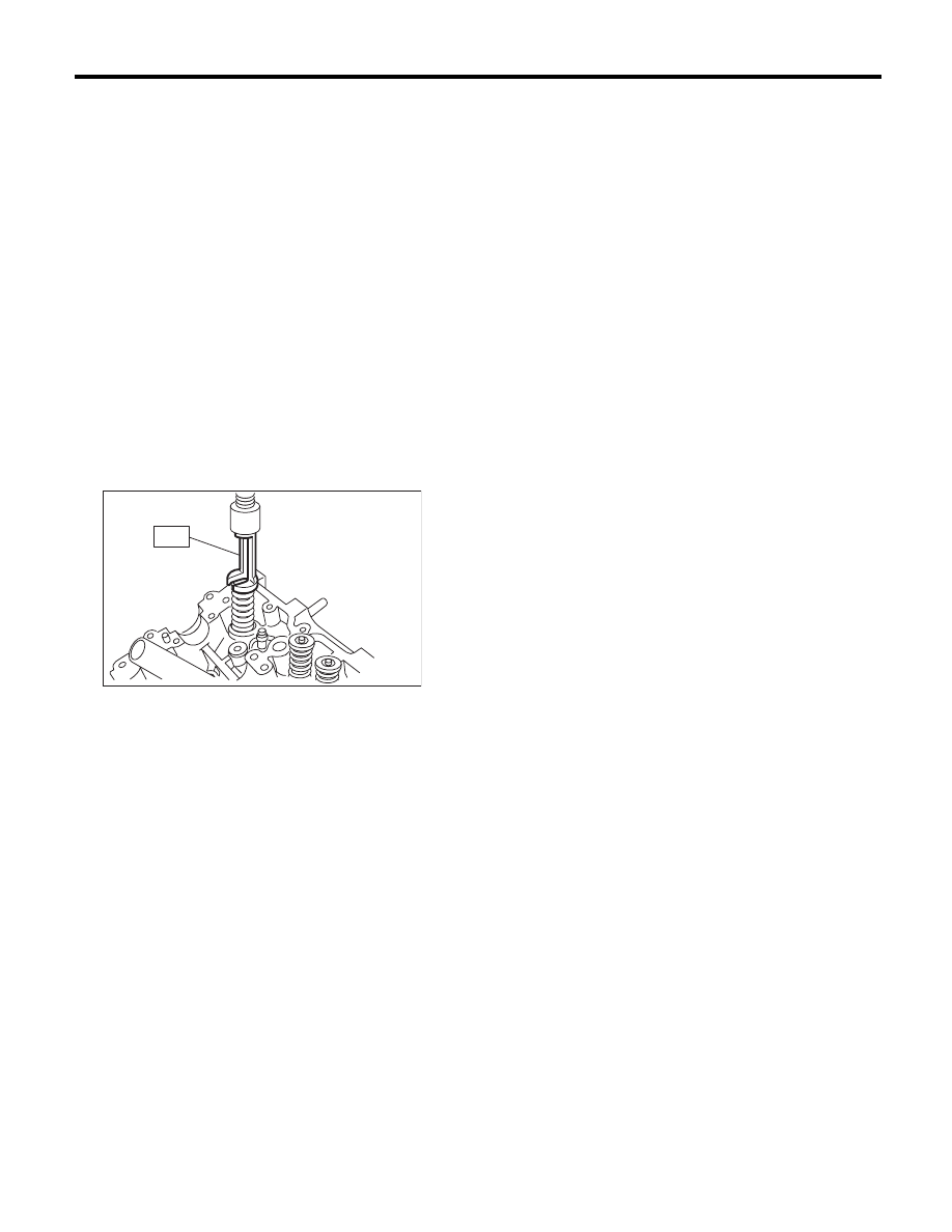
2) Compress the valve spring and remove the
valve spring retainer key using ST. Remove each
valve and valve spring.
ST

499718000

VALVE SPRING REMOVER

NOTE:
• Keep all the removed parts in order for re-install-
ing in their original positions.
• Mark each valve to prevent confusion.
• Pay careful attention not to damage the lips of in-
take valve oil seals and exhaust valve oil seals.
• For removal and installation procedures of the
valve guide, intake valve oil seal and exhaust valve
oil seal, refer to “Inspection”. <Ref. to ME(H4SO)-
63, VALVE GUIDE, INSPECTION, Cylinder
Head.> <Ref. to ME(H4SO)-66, INTAKE AND EX-
HAUST VALVE OIL SEAL, INSPECTION, Cylinder
Head.>

ME-00280

ST

ME(H4SO)-61

Cylinder Head

MECHANICAL

D: ASSEMBLY

(1)

Valve

(6)

Retainer

(11)

Plug

(2)

Valve guide

(7)

Retainer key

(12)

Camshaft cap

(3)

Valve spring seat

(8)

Spark plug gasket

(13)

Valve rocker ASSY

(4)

Oil seal

(9)

Camshaft

(14)

Seal washer

(5)

Valve spring

(10)

Oil seal


ME-03110

(10)

(9)

(6)

(1)

(2)

(3)

(4)

(5)

(7)

(8)

(11)

(13)

(14)

(12)

ME(H4SO)-62

Cylinder Head

MECHANICAL

1) Install the valve spring and valve.

(1) Coat the stem of each valve with engine oil
and insert the valve into the valve guide.

NOTE:
When inserting the valve into valve guide, use spe-
cial care not to damage the oil seal lip.

(2) Set the cylinder head on ST.

ST

498267800

CYLINDER HEAD TABLE

(3) Install the valve spring and retainer.

NOTE:
Be sure to install the valve spring with its close-
coiled end facing the seat on cylinder head.

(4) Set the ST on valve spring.

ST

499718000

VALVE SPRING REMOVER

(5) Compress the valve spring and fit the valve
spring retainer key.

(6) After installing, tap the valve spring retainers
lightly with a plastic hammer for better seating.

E: INSPECTION

1. CYLINDER HEAD

1) Check for cracks or damage. Use liquid pene-
trant tester on the important sections to check for
fissures. Check that there are no marks of gas leak-
ing or water leaking on gasket installing surface.
2) Place the cylinder head on the ST.
ST

498267800

CYLINDER HEAD TABLE

3) Measure the warping of the cylinder head sur-
face that mates with cylinder block using a straight
edge (A) and thickness gauge (B).
If the warping exceeds the limit, correct the surface
by grinding it with a surface grinder.

Warping limit:

0.035 mm (0.0014 in)

Grinding limit:

0.1 mm (0.004 in)

Standard height of cylinder head:

97.5 mm (3.84 in)

NOTE:
Uneven torque for the cylinder head bolts can
cause warping. When reassembling, pay special
attention to the torque so as to tighten evenly.

(A) Retainer key

(B) Valve spring

(C) Retainer

ME-00280

ST

ME-02816

(B)

(B)

(A)

(C)

(C)

ST

(A)

(B)

ME-00285

ME(H4SO)-63

Cylinder Head

MECHANICAL

2. VALVE SEAT

Inspect the intake and exhaust valve seats, and
correct the contact surfaces with a valve seat cutter
if they are defective or when valve guides are re-
placed.

Valve seat width W:

Standard:

Intake (A)

0.8 — 1.4 mm (0.03 — 0.055 in)

Exhaust (B)

1.2 — 1.8 mm (0.047 — 0.071 in)

3. VALVE GUIDE

1) Check the clearance between valve guide and
valve stem. The clearance can be checked by mea-
suring respectively the outer diameter of valve
stem with a micrometer and the inner diameter of
valve guide with a caliper gauge.

Clearance between the valve guide and valve
stem:

Standard:

Intake

0.035 — 0.062 mm (0.0014 — 0.0024 in)

Exhaust

0.040 — 0.067 mm (0.0016 — 0.0026 in)

2) If the clearance between the valve guide and
valve stem exceeds the standard, replace the valve
guide or valve itself, whichever shows greater
amount of wear or damage. See the following pro-
cedure for valve guide replacement.

Valve guide inner diameter:

6.000 — 6.012 mm (0.2362 — 0.2367 in)

Valve stem outer diameters:

Intake

5.950 — 5.965 mm (0.2343 — 0.2348 in)

Exhaust

5.945 — 5.960 mm (0.2341 — 0.2346 in)

(1) Place the cylinder head on ST1 with the
combustion chamber upward so that valve
guides fit the holes in ST1.

W

W

(A)

(B)

ME-00397

ME-00287

(A) Valve guide

ME-00763

(A)

ME-00289

X

Y


Content   ..  64  65  66  67   ..