Subaru Legacy IV (2008 year). Manual - part 64


  Index      Subaru     Subaru Legacy IV - service repair manual 2008 year


Search            


Content   ..  62  63  64  65   ..


Subaru Legacy IV (2008 year). Manual - part 64


ME(H4SO)-52

Valve Rocker Assembly

MECHANICAL

B: INSTALLATION

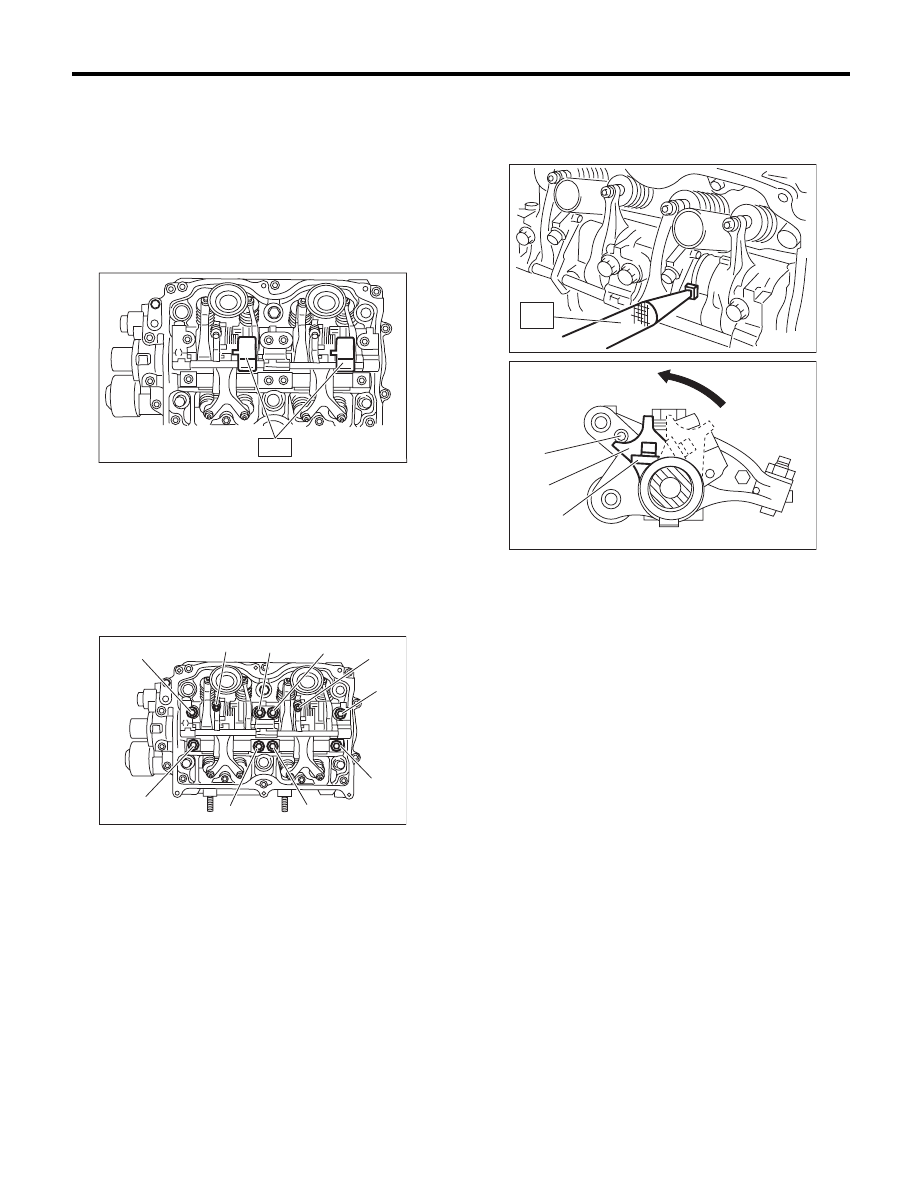
1) Install the valve rocker assembly.

(1) Temporarily tighten the bolts equally in al-
phabetical order as shown in the figure.

NOTE:
• Do not temporarily tighten the bolts (i) and (j).
• Set the ST in the position shown in the drawing to
mount the intake valve rocker assembly.
ST

18354AA000

VALVE ROCKER HOLDER

(2) Tighten the bolts (a) through (h) to specified
torque.

Tightening torque:

25 N·m (2.5 kgf-m, 18.4 ft-lb)

(3) Tighten the bolts (i) through (j) to specified
torque.

Tightening torque:

6 N·m (0.6 kgf-m, 4.4 ft-lb)

(4) Use the ST to rotate the spring stopper in
the direction of the arrow to fasten the adjuster
pin.

ST

18258AA000

SPRING INSTALLER

2) Remove the timing belt cover LH.
3) Adjust the valve clearance. <Ref. to ME(H4SO)-
28, ADJUSTMENT, Valve Clearance.>
4) Install the timing belt cover LH.
5) Install the rocker cover.

(1) Install the rocker cover gasket to the rocker
cover.

NOTE:
Use a new rocker cover gasket.

(2) Temporarily tighten the bolts in alphabetical
order shown in the figure, tighten them in two
stages.

Tightening torque:

1st

6.4 N·m (0.7 kgf-m, 4.7 ft-lb)

2nd (only (a) and (b) are tightened)

6.4 N·m (0.7 kgf-m, 4.7 ft-lb)

ME-02794

ST

(g)

(i)

(a)

(c)

(j)

(e)

(h)

(b)

(d)

(f)

ME-02703

(A) Adjuster pin

(B) Spring stopper

(C) Spring

ST

ME-02704

(C)

(B)

(A)

ME-02705

ME(H4SO)-53

Valve Rocker Assembly

MECHANICAL

RH side

LH side

(3) Connect the PCV hose.

6) Install the high tension cord.

C: DISASSEMBLY

NOTE:
Intake valve rocker assembly cannot be disassem-
bled.
1) Remove the exhaust valve rocker arm from the
rocker shaft.

NOTE:
Keep all the removed parts in order for re-installing
in their original positions.
2) Remove the nut and adjusting screw from ex-
haust valve rocker.

D: ASSEMBLY

NOTE:
Intake valve rocker assembly cannot be disassem-
bled.
1) Install the adjusting screw and nut to the exhaust
valve rocker.
2) Insert the exhaust valve rocker arm to rocker
shaft.

NOTE:
Valve rocker arms, and rocker shaft have identifica-
tion marks. Make sure the parts with same mark-
ings are properly assembled.

E: INSPECTION

1. INTAKE VALVE ROCKER ASSEMBLY

1) If the roller or valve contact surface of valve
rocker arm is worn or dented excessively, replace
the valve rocker assembly.
2) Check that the valve rocker arm roller rotates
smoothly. If not, replace the valve rocker assembly.

2. EXHAUST VALVE ROCKER ASSEMBLY

1) Measure the inner diameter of valve rocker arm
and outer diameter of valve rocker shaft, and con-
firm the difference (oil clearance) between the two
values.

Clearance between arm and shaft:

Standard

0.020 — 0.054 mm (0.0008 — 0.0021 in)

2) If the oil clearance exceeds the limit, replace the
valve rocker arm or shaft, whichever shows the
greater amount of wear.

Rocker arm inside diameter:

22.020 — 22.041 mm (0.8669 — 0.8678 in)

Rocker shaft diameter:

21.987 — 22.000 mm (0.8656 — 0.8661 in)

3) If the roller or valve contact surface of valve
rocker arm is worn or dented excessively, replace
the valve rocker arm.
4) Check that the valve rocker arm roller rotates
smoothly. If not, replace the valve rocker arm.

ME-02715

(a)

(b)

(c)

(d)

(e)

(f)

ME-02716

(a)

(b)

(c)

(d)

(e)

(f)

ME-02706

ME-00257

ME(H4SO)-54

Camshaft

MECHANICAL

19.Camshaft

A: REMOVAL

NOTE:
When replacing the single part, perform the work
with the engine installed to body. Refer to “Valve
Clearance” for preparation procedures. <Ref. to
ME(H4SO)-27, Valve Clearance.>
1) Remove the V-belts. <Ref. to ME(H4SO)-38,
REMOVAL, V-belt.>
2) Remove the crank pulley. <Ref. to ME(H4SO)-
41, REMOVAL, Crank Pulley.>
3) Remove the timing belt cover. <Ref. to
ME(H4SO)-43, REMOVAL, Timing Belt Cover.>
4) Remove the timing belt. <Ref. to ME(H4SO)-44,
REMOVAL, Timing Belt.>
5) Remove the cam sprocket. <Ref. to ME(H4SO)-
49, REMOVAL, Cam Sprocket.>
6) Remove the timing belt cover No. 2 LH.
7) Remove the timing belt cover No. 2 RH.

NOTE:
Do not damage or lose the seal rubber when re-
moving the timing belt covers.

8) Remove the tensioner bracket.

9) Remove the camshaft position sensor support.
(LH side only)
10) Remove the valve rocker assembly. <Ref. to
ME(H4SO)-51, REMOVAL, Valve Rocker Assem-
bly.>

11) Remove the camshaft cap.

(1) Remove the bolts (a) and (b) in alphabetical
sequence.

(2) Equally loosen the bolts (c) through (j) all the
way in alphabetical sequence.

(3) Remove the bolts (k) through (p) in alpha-
betical sequence using ST.

ST

499497000

TORX

®

 PLUS

(4) Remove the camshaft cap.

12) Remove the camshaft.
13) Remove the oil seal.
14) Remove the plug from rear side of camshaft.

CAUTION:
Do not scratch the journal surface when remov-
ing the oil seal.
15) Similarly, remove the camshaft RH and related
parts.

ME-00258

ME-00259

(a)

(b)

ME-02707

ME-02708

(d)

(j)

(h)

(f)

(e)

(i)

(g)

(c)

(n)

(p)

(l)

(o)

(m)

(k)

ME-02709

ME(H4SO)-55

Camshaft

MECHANICAL

B: INSTALLATION

1) Apply a thin coat of engine oil to camshaft jour-
nals, and install the camshaft.
2) Install the camshaft cap.

(1) Apply liquid gasket to the mating surfaces of
camshaft cap.

NOTE:
Install within 5 minutes after applying liquid gasket.

Liquid gasket:

THREE BOND 1217G (Part No. K0877Y0100) 
or equivalent

NOTE:
Apply a coat of liquid gasket of 3 mm (0.12 in) in di-
ameter (A) along the edge (B) of camshaft cap (C)
mating surface.

(2) Temporarily tighten the bolts (a) through (d)
in alphabetical sequence.

(3) Install the valve rocker assembly. <Ref. to
ME(H4SO)-52, INSTALLATION, Valve Rocker
Assembly.>

(4) Tighten the TORX

®

 bolts (e) through (j) in al-

phabetical sequence using ST.

ST

499497000

TORX

®

 PLUS

Tightening torque:

18 N·m (1.8 kgf-m, 13.3 ft-lb)

(5) Tighten the bolts (k) through (r) in alphabet-
ical sequence.

Tightening torque:

9.75 N·m (1.0 kgf-m, 7.2 ft-lb)

(6) Tighten the bolts (s) and (t) in alphabetical
sequence.

NOTE:
• Use new seal washer.
• Install and tighten the seal washer to the bolt.

Tightening torque:

9.75 N·m (1.0 kgf-m, 7.2 ft-lb)

ME-02710

ME-00265

(A)

(B)

(C)

(d)

(a)

(b)

(c)

ME-02711

(g)

(e)

(i)

(f)

(h)

(j)

ME-02712

ME-02713

(q)

(k)

(m)

(o)

(p)

(l)

(n)

(r)

(s)

(t)

ME-02714


Content   ..  62  63  64  65   ..