Subaru Legacy IV (2008 year). Manual - part 59


  Index      Subaru     Subaru Legacy IV - service repair manual 2008 year


Search            


Content   ..  57  58  59  60   ..


Subaru Legacy IV (2008 year). Manual - part 59


ME(H4SO)-32

Engine Assembly

MECHANICAL

24) Support the transmission with a garage jack.

CAUTION:
Be sure to always perform this work, in order to
prevent the transmission from lowering for its
own weight.

25) Separation of engine and transmission

CAUTION:
Before removing the engine away from trans-
mission, check to be sure no work has been
overlooked.

(1) Remove the starter. <Ref. to SC(H4SO)-6,
REMOVAL, Starter.>
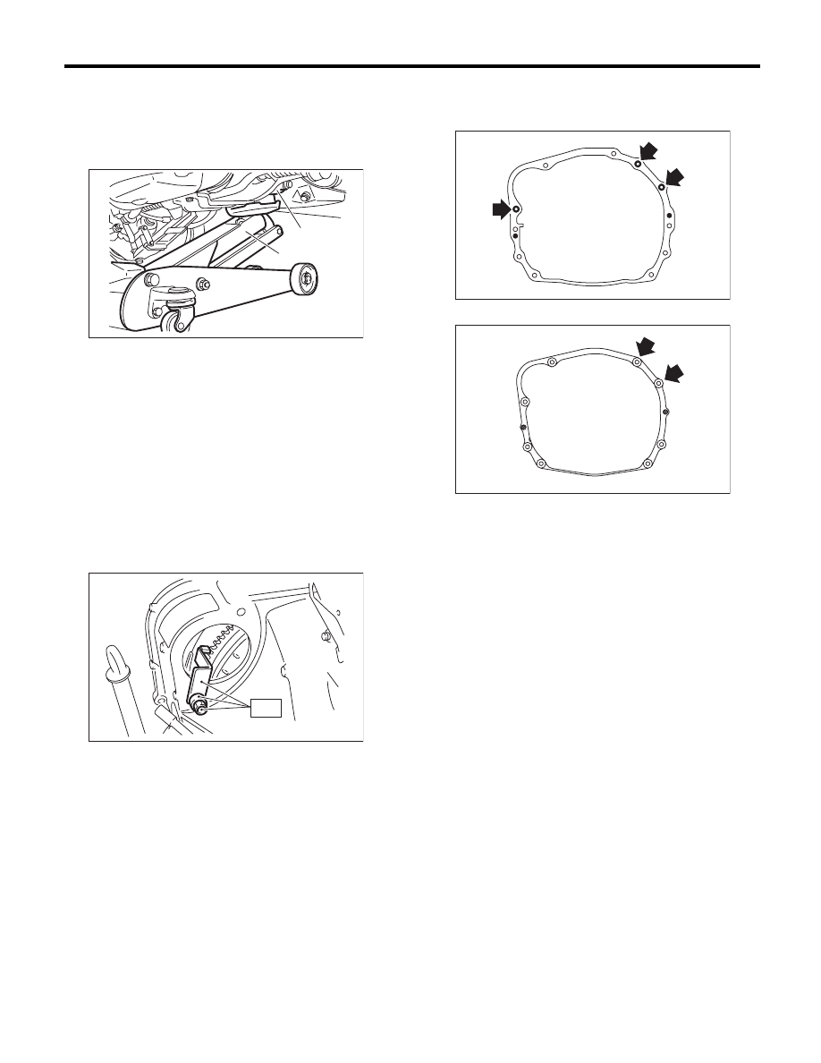
(2) Attach the ST to the torque converter clutch
case. (AT model)

ST

498277200

STOPPER SET

(3) Remove the bolts which hold upper side of
transmission to engine.
• AT model

• MT model

26) Remove the engine from vehicle.

(1) Slightly raise the engine.
(2) Raise the transmission with garage jack.
(3) Move the engine horizontally until main
shaft is withdrawn from clutch cover. (MT mod-
el)
(4) Slowly move the engine away from engine
compartment.

NOTE:
Be careful not to damage adjacent parts or body
panels with crank pulley, oil level gauge, etc.
27) Remove the engine mounting from the engine.

(A) Transmission

(B) Garage jack

ME-00215

(B)

(A)

ST

ME-00217

AT-00106

MT-01524

ME(H4SO)-33

Engine Assembly

MECHANICAL

B: INSTALLATION

1) Install the engine mounting onto the engine.

Tightening torque:

35 N·m (3.6 kgf-m, 25.8 ft-lb)

2) Apply a small amount of grease to splines of
main shaft. (MT model)

Grease:

NICHIMOLY N-130 or equivalent

3) Position the engine in engine compartment and
align it with transmission.

NOTE:
Be careful not to damage adjacent parts or body
panels with crank pulley, oil level gauge, etc.
4) Tighten the bolts which hold upper side of trans-
mission to engine.

Tightening torque:

50 N·m (5.1 kgf-m, 36.9 ft-lb)

• AT model

• MT  model

5) Remove the lifting device and wire ropes.

6) Remove the garage jack.

7) Install the pitching stopper.

Tightening torque:

T1: 50 N·m (5.1 kgf-m, 36.9 ft-lb)
T2: 58 N·m (5.9 kgf-m, 42.8 ft-lb)

8) Remove the ST from the torque converter clutch
case. (AT model)

NOTE:
Be careful not to drop the ST into the torque con-
verter clutch case when removing the ST.
ST

498277200

STOPPER SET

9) Install the starter. <Ref. to SC(H4SO)-6, IN-
STALLATION, Starter.>
10) Install the torque converter clutch to drive plate.
(AT model)

(1) Insert the wrench into the crank pulley bolt
and rotate the crank pulley to tighten the bolts
which hold torque converter clutch to drive plate.

NOTE:
Be careful not to drop bolts into the torque convert-
er clutch case.

Tightening torque:

25 N·m (2.5 kgf-m, 18.4 ft-lb)

(2) Install the service hole plug.

AT-00106

MT-01524

LU-00222

T2

T1

AT-03878

ST

ME-00217

ME-00212

ME(H4SO)-34

Engine Assembly

MECHANICAL

11) Install the power steering pump.

(1) Install the power steering pump.

Tightening torque:

Refer to “COMPONENT” of “Power Steering” 
for the tightening torque. <Ref. to PS-3, COM-
PONENT, General Description.>

(2) Connect the power steering pump switch
connector.

(3) Install and adjust the front side belt. <Ref. to
ME(H4SO)-39, FRONT SIDE BELT, INSTAL-
LATION, V-belt.>

12) Lift up the vehicle.
13) Tighten the bolts and nuts which hold lower
side of the transmission to engine.

Tightening torque:

50 N·m (5.1 kgf-m, 36.9 ft-lb)

• AT model

• MT model

14) Tighten the nuts which hold the engine mount
to the crossmember.

Tightening torque:

75 N·m (7.6 kgf-m, 55.3 ft-lb)

15) Connect the ground cable.

Tightening torque:

7.5 N·m (0.8 kgf-m, 5.5 ft-lb)

16) Install the front and center exhaust pipe. <Ref.
to EX(H4SO)-5, INSTALLATION, Front Exhaust
Pipe.>
17) Lower the vehicle.

ME-00037

ME-03004

AT-00108

MT-00077

LU-02470

ME-03376

ME-03377

ME(H4SO)-35

Engine Assembly

MECHANICAL

18) Connect the following hoses.

(1) Fuel delivery hose and evaporation hose
(2) Heater inlet and outlet hoses
(3) Brake booster vacuum hose

19) Connect the following connectors and termi-
nals.

(1) Front oxygen (A/F) sensor connector
(2) Rear oxygen sensor connector
(3) Engine harness connectors

Tightening torque:

6.4 N·m (0.7 kgf-m, 4.7 ft-lb)

(4) Generator connector and terminal

Tightening torque:

15 N·m (1.5 kgf-m, 11.1 ft-lb)

(5) A/C compressor connector

20) Install the air intake chamber stay.

Tightening torque:

16 N·m (1.6 kgf-m, 11.8 ft-lb)

21) Install the A/C pressure hoses. <Ref. to AC-40,
INSTALLATION, Hose and Pipe.>
22) Install the radiator to vehicle. <Ref. to
CO(H4SO)-20, INSTALLATION, Radiator.>
23) Install the air intake duct, air cleaner case and
air intake chamber. <Ref. to IN(H4SO)-8, INSTAL-
LATION, Air Intake Duct.> <Ref. to IN(H4SO)-6,
INSTALLATION, Air Cleaner Case.> <Ref. to
IN(H4SO)-7, INSTALLATION, Air Intake Cham-
ber.>
24) Install the under cover.
25) Install the battery. <Ref. to SC(H4SO)-20, IN-
STALLATION, Battery.>
26) Fill engine coolant. <Ref. to CO(H4SO)-13,
FILLING OF ENGINE COOLANT, REPLACE-
MENT, Engine Coolant.>
27) Check the ATF level and replenish it if neces-
sary. (AT model) <Ref. to 4AT-26, INSPECTION,
Automatic Transmission Fluid.>
28) Charge the A/C system with refrigerant. <Ref.
to AC-23, PROCEDURE, Refrigerant Charging
Procedure.>

29) Install the V-belt cover.

Tightening torque:

13 N·m (1.3 kgf-m, 9.6 ft-lb)

30) Remove the front hood stay, and close the front
hood.
31) Lower the vehicle from lift.

C: INSPECTION

1) Check that pipes, hoses, connectors and clamps
are installed firmly.
2) Check the engine coolant is at specified level.
3) Check the ATF is at specified level. (AT model)
4) Start the engine and check for exhaust gas, en-
gine coolant, leaks of fuel, etc. Also check for noise
and vibrations.

FU-03924

ME-03945


Content   ..  57  58  59  60   ..